Raman spectroscopic system with integrating cavity

Inactive Publication Date: 2005-12-13
TYCO HEALTHCARE GRP LP
View PDF11 Cites 69 Cited by
  • Summary
  • Abstract
  • Description
  • Claims
  • Application Information

AI Technical Summary

Benefits of technology

[0019]The present invention provides an apparatus capable of efficiently collecting Raman scattered electromagnetic radiation from large samples, using high power exciting radiation without damaging the sample and by providing exciting radiation that is expanded or scattered prior to reaching the sample, thus avoiding high local power density on any part of

Problems solved by technology

For any given detector both these values are predefined and they set a physical limit to the collecting efficiency of the optical system.
Unfortunately, because of the high power density required, this approach can result in damage to live tissues and cannot be routinely used for in-vivo medical diagnosis (see for example U.S. Pat. No. 5,553,616).
Unfortunately, because of a competing fluorescence effect, application of radiation from the visible and UV ranges is also undesirable.
Furthermore, only a small part of the radiation can be collected due to limited capabilities of radiation collecting systems.
As a result, the collected Raman signal is very weak and a lot of effort has been undertaken to increase the collecting efficiency of the applied optical system by increasing the collecting angle as much as possible.
Unfortunately, this strategy has not met with much success for two main reasons.
In practice the collecting angle is usually many times smaller because of technical limitations.
The second is that an increase in the collecting angle reduces the area and volume of the sample from which the scattered radiation can be efficiently collected.
In this situation, illumination with exciting radiation of the sample area that is larger than that, from which the scattered radiation can be effectively collected, is wasteful and should not be applied.
Therefore the option of increasing the signal through improvement of the collecting capability of the optica

Method used


Image

  • Raman spectroscopic system with integrating cavity
  • Raman spectroscopic system with integrating cavity
  • Raman spectroscopic system with integrating cavity

Examples


Embodiment Construction

[0049]The present invention relates to the field of non-invasive spectroscopic characterization and measurements of the chemical composition of samples. More specifically the invention relates to the use of Raman spectroscopy and an integrating cavity for the analysis of samples.

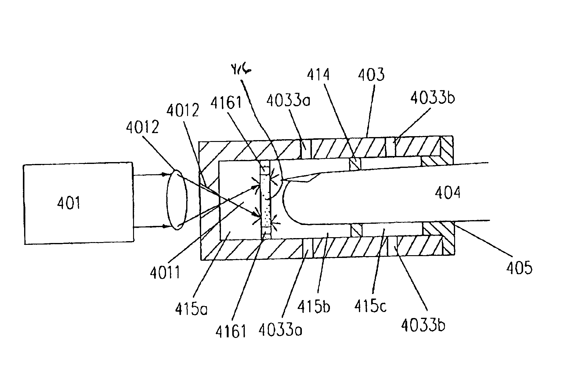
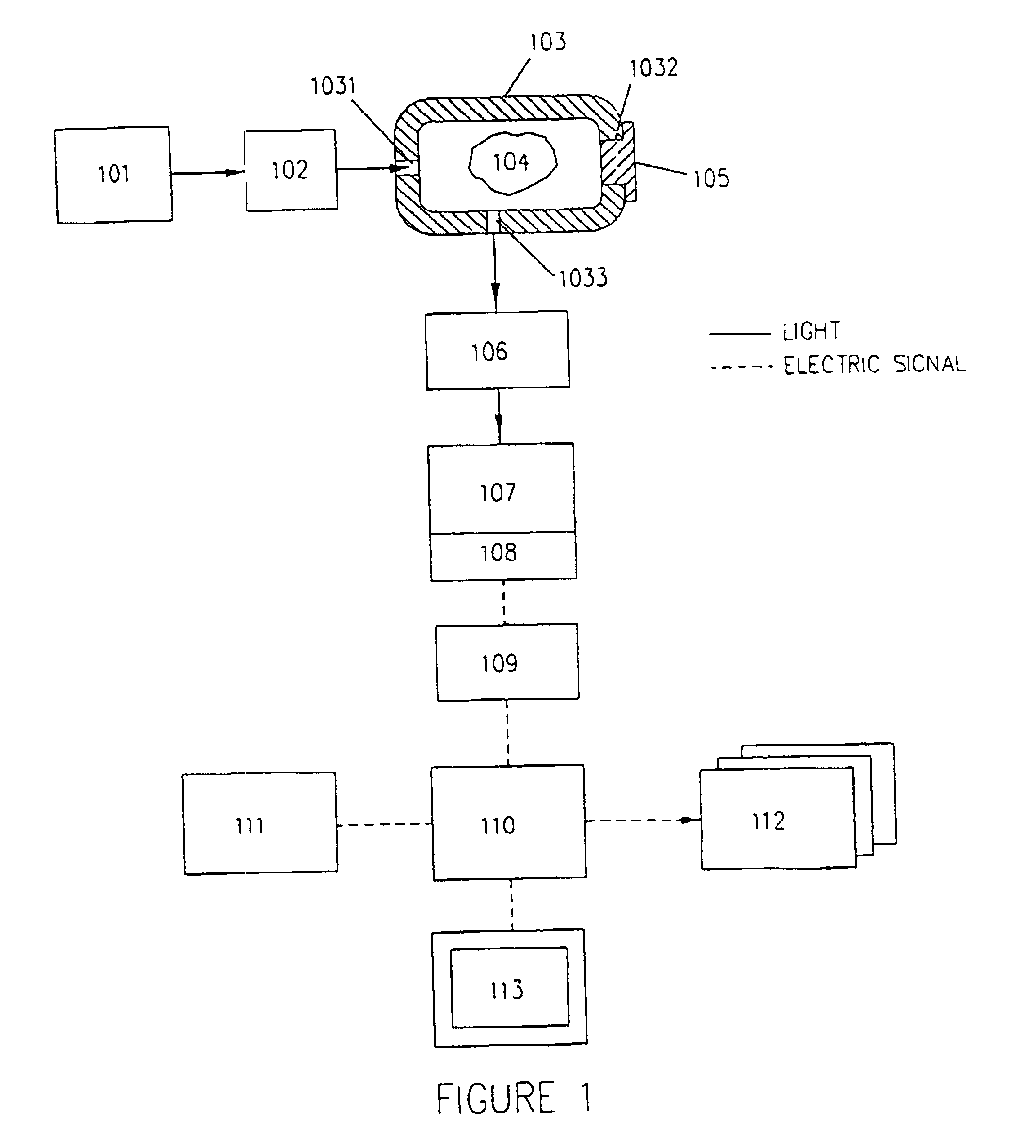
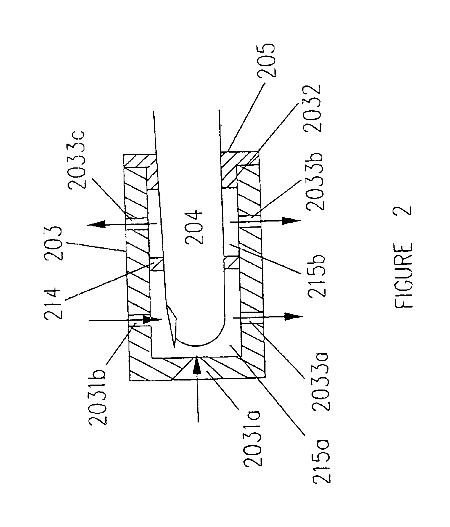
[0050]The invention provides an apparatus capable of efficiently collecting Raman scattered electromagnetic radiation from a range of samples, including large samples that have been excited with high level of total power of radiation. In this case, the high power beam of electromagnetic radiation is expanded prior to reaching the sample, thus avoiding high local intensity on any part of the sample.

[0051]The following description is of a preferred embodiment by way of example only and without limitation to the combination of features necessary for carrying the invention into effect.

[0052]According to one aspect of the present invention, Raman spectroscopy may be used to characterize the chemical composition o...


PUM


Abstract

The present invention provides an apparatus for measurement of Raman scattered radiation comprising. The apparatus comprises at least one source of electromagnetic radiation for producing an electromagnetic radiation beam characterized by a narrow spectral width, an integrating cavity having an interior and an exterior, wherein a sample is placed in said interior. The integrating cavity further having at least one port for insertion of the sample in the interior and for transmission of the electromagnetic radiation into and out from the interior, the at least one port extending from the exterior to said interior of said integrating cavity. The integrating cavity also comprises a first optical element for transmitting the electromagnetic radiation into the interior of the integrating cavity through the at least one port, and a second optical element for collecting Raman scattered electromagnetic radiation from the sample through the at least one port. The apparatus also comprises a spectrum analyzer for determining spectral composition of the Raman scattered electromagnetic radiation, a detector for measuring the Raman scattered electromagnetic radiation; and a system for determining concentration of at least one chemical compound from the measured Raman scattered electromagnetic radiation. The apparatus may also comprise a radiation expanding element. A method for measuring the concentration of one or more chemical compounds in a sample using Raman scattering is also provided.

Description

FIELD OF INVENTION[0001]The invention relates to the field of non-invasive spectroscopic measurements of samples. More specifically the invention relates to the use of Raman spectroscopy for the analysis of samples.BACKGROUND OF INVENTION[0002]Raman spectroscopy is concerned with the phenomenon of a frequency change when photons of electromagnetic radiation are inelastically scattered by molecules. If the frequency of incident electromagnetic radiation is νo and that of scattered electromagnetic radiation is νr, then the magnitude of the frequency shift or Raman shift νo−νr=Δν is referred to as Raman frequency. The Raman process can be understood by assuming incident electromagnetic radiation consists of photons with energy hνo. On collision with molecules, a photon may be elastically scattered without change of energy. This gives rise to the so-called “Rayleigh” scattering signal. In some cases, called inelastic, the collision causes the electromagnetic radiation scattering molecul...

Claims


Application Information

Patent Timeline
IPC IPC(8): A61B5/00G01N21/65
CPCA61B5/14532A61B5/14546A61B5/1455A61B5/6826A61B5/6838G01N21/65G01N2021/651G01N2201/06126G01N2201/065
Inventor PAWLUCZYK, ROMUALD
Owner TYCO HEALTHCARE GRP LP
Why Eureka
Try Eureka