Modified X-ray tube for use in the presence of magnetic fields

a magnetic field and x-ray tube technology, applied in the field of medical systems, can solve the problems of inability to use near, let alone inside, a mri system, and the patient is moved

Inactive Publication Date: 2005-12-13
THE BOARD OF TRUSTEES OF THE LELAND STANFORD JUNIOR UNIV
View PDF15 Cites 30 Cited by
  • Summary
  • Abstract
  • Description
  • Claims
  • Application Information

AI Technical Summary

Benefits of technology

[0014]Accordingly, the present invention provides a combined MRI and x-ray fluoroscopy system using a modified x-ray source that improves the control of the direction of the electron beam onto the x-ray tube target. Deflection of the electron beam by the static magnetic field is reduced or eliminated. The present invention also provides a modified x-ray tube for use in a magnetic field. The modified x-ray tube contains various additions for steering the electron beam onto the anode target, and therefore has an increased robustness to magnetic fields in comparison with conventional x-ray tubes.
[0015]Specifically, the present invention provides an imaging system containing a magnetic resonance imaging (MRI) system and an x-ray fluoroscopy system, each having a respective field of view (FOV). Ideally, the MRI and x-ray fields of view are substantially coincident, so that an object being imaged does not need to be moved to acquire both types of image, but this need not be the case. Preferably, the MRI system is an interventional MRI system, and the x-ray system is positioned within an open bore of the MRI system. The MRI system contains a magnet for generating a static magnetic field. The x-ray system contains an x-ray source having an x-ray tube for generating x-rays by accelerating an electron beam onto an anode target. The x-ray tube is in the presence of the static magnetic field. A stationary anode x-ray tube is preferred due to its more compact size, but a rotating anode tube can also be used. The x-ray source also contains means for steering the electron beam onto the anode target. Preferably, the x-ray tube is positioned so that the electron beam is substantially parallel to the static magnetic field, minimizing the amount of beam steering required to steer the electron beam onto the target. Ideally, the x-ray system also has mostly non-magnetic components and therefore does not significantly distort the static magnetic field of the MRI system.
[0019]The different embodiments of the invention all allow for some control of the steering or aiming of the electron beam in the x-ray tube without requiring careful alignment of the x-ray tube with the static magnetic field of the MRI system. As a result, the x-ray tube can be placed within the main magnetic field of the MRI system.

Problems solved by technology

Moving the patient is undesirable, because it is time consuming, possibly dangerous, and can render the images inconsistent.
For example, conventional x-ray fluoroscopy detectors are image intensifiers, which are exceedingly sensitive to magnetic fields and therefore cannot be used near, let alone inside, an MRI system.
A major obstacle to combining MRI and x-ray systems is the x-ray source, which consists of an x-ray tube and its housing.
Thus the effect of the static magnetic field of the MRI system on the x-ray tube can be highly undesirable and may damage the tube if it is operated under non-ideal conditions, or it may lower the x-ray intensity to a level that is unacceptable.
In the combined system, it is not desirable—indeed it may be impossible—to turn off the static magnetic field before acquiring x-ray images, and so the effect of the magnetic field on the x-ray tube must be addressed.
Sufficient cladding to completely eliminate the effect of the magnetic field on the electron beam may not be feasible.
Aligning the tube with the field also has potential problems.
First, the alignment may be very critical, i.e., have a very small tolerance, making it difficult to attain.
Second, x-ray tube inserts typically have components that distort the magnetic field and pose additional difficulties that cannot be solved simply by aligning the electron beam with the magnetic field.
The alignment also constrains the image plane, potentially to undesired orientations.

Method used


Image

  • Modified X-ray tube for use in the presence of magnetic fields
  • Modified X-ray tube for use in the presence of magnetic fields
  • Modified X-ray tube for use in the presence of magnetic fields

Examples


first embodiment

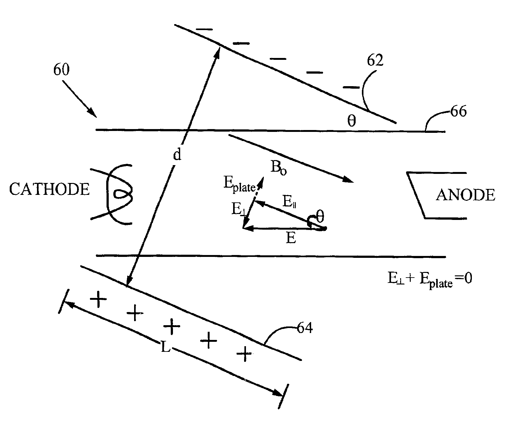
[0040]FIG. 4 shows an x-ray source 60 of the invention, referred to as the electrostatic deflection embodiment. In the x-ray source 60, the electron beam is steered 30 using electrostatic plates 62 and 64 around an x-ray tube 66 and separated by a distance d. The plates 62 and 64 are parallel to each other and at an angle θ with the axis of the tube 66. θ is the angle between the main magnetic field B0 and the electric field between the anode and cathode; that is, the plates 62 and 64 are parallel to B0. An electric potential V is applied between the two plates, creating an approximately uniform electric field Eplate of magnitude V / d within the tube. The electric field Eplate exerts a force on an electron in the beam of magnitude FE=eV / d, where e is the electron charge, directed toward the higher potential plate. The position of and electric potential between the plates 62 and 64 is selected to oppose the component of the main electric field E (between anode and cathode) that is per...

second embodiment

[0043]FIG. 5 shows an x-ray source 70 of the present invention, referred to as the electromagnetic deflection embodiment. In this embodiment, the electron beam is steered toward the target using an electromagnet, coils 72 positioned around the outside of an x-ray tube 74. Each coil 72 contains N turns of wire, and the coils are separated by their radius r. Current flowing through the coils 72 generates an additional magnetic field Bcoil within the tube 74 that opposes the component of the static magnetic field perpendicular to the tube axis. Optimal focusing of the electron beam on the target is provided when the net magnetic field in the tube is directed along the tube axis, i.e., when the component of the magnetic field perpendicular to the tube axis is zero. In the electromagnetic deflection embodiment, the current I in the coils 72 is selected so that the sum of the coil magnetic field Bcoil and the static magnetic field B0 is directed only along the tube axis. For example, as s...

third embodiment

[0053]an x-ray source 80 is shown in FIG. 6. In this embodiment, a small amount of magnetic material 82 is placed behind the anode 84 of the x-ray tube 86, i.e., on the side opposite the side on which the electrons collide with the target. Because the magnetic material 82 has a large magnetization in the applied magnetic field, it distorts the local magnetic field lines near the anode 84 so that more magnetic field lines go through the focal spot on the target. The locally distorted magnetic field acts to increase the focusing of the electrons on the anode target. Any suitable magnetic material can be used.


PUM


Abstract

An imaging system and method combines a magnetic resonance imaging (MRI) system and an x-ray fluoroscopy system such that the two systems have coincident fields of view. X-rays are generated by a stationary anode x-ray tube in which an electron beam is accelerated from a cathode to an anode. In the presence of the static magnetic field of the MRI system, the electron beam is deflected unless it is parallel to the static magnetic field. The x-ray source of the invention contains elements used to steer the electron beam and increase its focusing on the anode. The beam can be steered electrostatically, electromagnetically, or by adding magnetic material to the x-ray source. In the resulting system, MR and x-ray images are acquired without moving the object, which is particularly useful for image-guided medical intervention procedures.

Description

CROSS-REFERENCE TO RELATED APPLICATIONS[0001]This application claims the benefit of U.S. Provisional Application Nos. 60 / 193,731 and 60 / 193,735, both filed Mar. 30, 2000, both of which are herein incorporated by reference.STATEMENT REGARDING FEDERALLY SPONSORED RESEARCH OR DEVELOPMENT[0002]This invention was supported in part by grant number P41 RR09784 from the National Institutes of Health (NIH). The U.S. Government has certain rights in the invention.FIELD OF THE INVENTION[0003]This invention relates generally to medical systems and methods for visualizing the human body and medical interventional devices. More particularly, it relates to an apparatus combining magnetic resonance imaging (MRI) and x-ray imaging in the same location using a modified x-ray tube.BACKGROUND ART[0004]Magnetic resonance imaging (MRI) and x-ray fluoroscopic imaging are important medical visualization tools used for image-guided interventional procedures. Each method provides its own advantages: MRI prov...

Claims


Application Information

Patent Timeline
Patent Type & Authority Patents(United States)
IPC IPC(8): H01J35/14H01J35/16H05C1/02
CPCH01J35/14H01J35/16H05C1/02G01R33/4812H01J35/153
Inventor PELC, NORBERT J.FAHRIG, REBECCAALLEY, MARCUS T.WEN, ZHIFEI
Owner THE BOARD OF TRUSTEES OF THE LELAND STANFORD JUNIOR UNIV
Why Eureka
Try Eureka