Error detecting method and device, information storing and reproducing device and magnetic disk drive

a technology of error detection and information storing, applied in the field of error detection methods and devices, information storing and reproducing devices and magnetic disk drives, can solve the problems of not being suited for storing information, affecting the reliability of information storing devices, and affecting the performance of detecting, so as to reduce the steps for detecting defects, improve the reliability of information storing devices, and improve the effect of detecting performan

Inactive Publication Date: 2005-12-13
HITACHI GLOBAL STORAGE TECH JAPAN LTD
View PDF5 Cites 10 Cited by
  • Summary
  • Abstract
  • Description
  • Claims
  • Application Information

AI Technical Summary

Benefits of technology

[0020]When the pattern collation for detecting defect cannot be conducted due to an error, then, this is registered as a defect to maintain margin for the defect in the data-synchronizing signal portion in order to improve reliability of the information storing device. When a defect is detected, further, the pattern collation can be conducted at one time by the pattern collation means for detecting defect over a range including regions preceding and succeeding the data-synchronizing signal. Therefore, the defect can be detected inclusive of a portion where a change in the rotation is taken into consideration making it possible to decrease the steps for detecting defects.
[0021]Further, a defect can be detected in advance in the region for storing the data-synchronizing signal inclusive of a portion of taking a change in the rotation into consideration, and only those sectors free of defect can be used for the region of storing the data-synchronizing signal. In really storing or reproducing information, therefore, no defect is involved in the detection of the data-synchronizing signal and, hence, attention may be given to the deterioration of the signals due to noise. Therefore, error little occurs in detecting the data-synchronizing signals, thereby to improve performance for detecting the data-synchronizing signals. Further, an increment in the performance for detecting the data-synchronizing signals can be utilized for maintaining performance for detecting the data-synchronizing signals while decreasing the region for the data-synchronizing signals. In this case, the region for the data-syn

Problems solved by technology

The defect region occurs when the magnetic material for storing information is not uniformly spread on the storing surface in the step of production, when information is not stored due to dirt and scars on the storing surface, when signals for reproducing information are not produced to a sufficient degree or when large noise is superposed on the reproducing signals.
The defect region usually maintains undesired properties and is not suited for storing information up to the future or for reproducing information.
Namely, this method is to suppress defect at the time of reproducing information, and permits much defect.
Therefore, permitting the occurrence of much defect is not suited for detecting defects.
However, error is not corrected for the portions where the data synchronizing signals are stored for synchronizing the data.
Therefore, the data synchronizing signal

Method used


Image

  • Error detecting method and device, information storing and reproducing device and magnetic disk drive
  • Error detecting method and device, information storing and reproducing device and magnetic disk drive
  • Error detecting method and device, information storing and reproducing device and magnetic disk drive

Examples


first embodiment

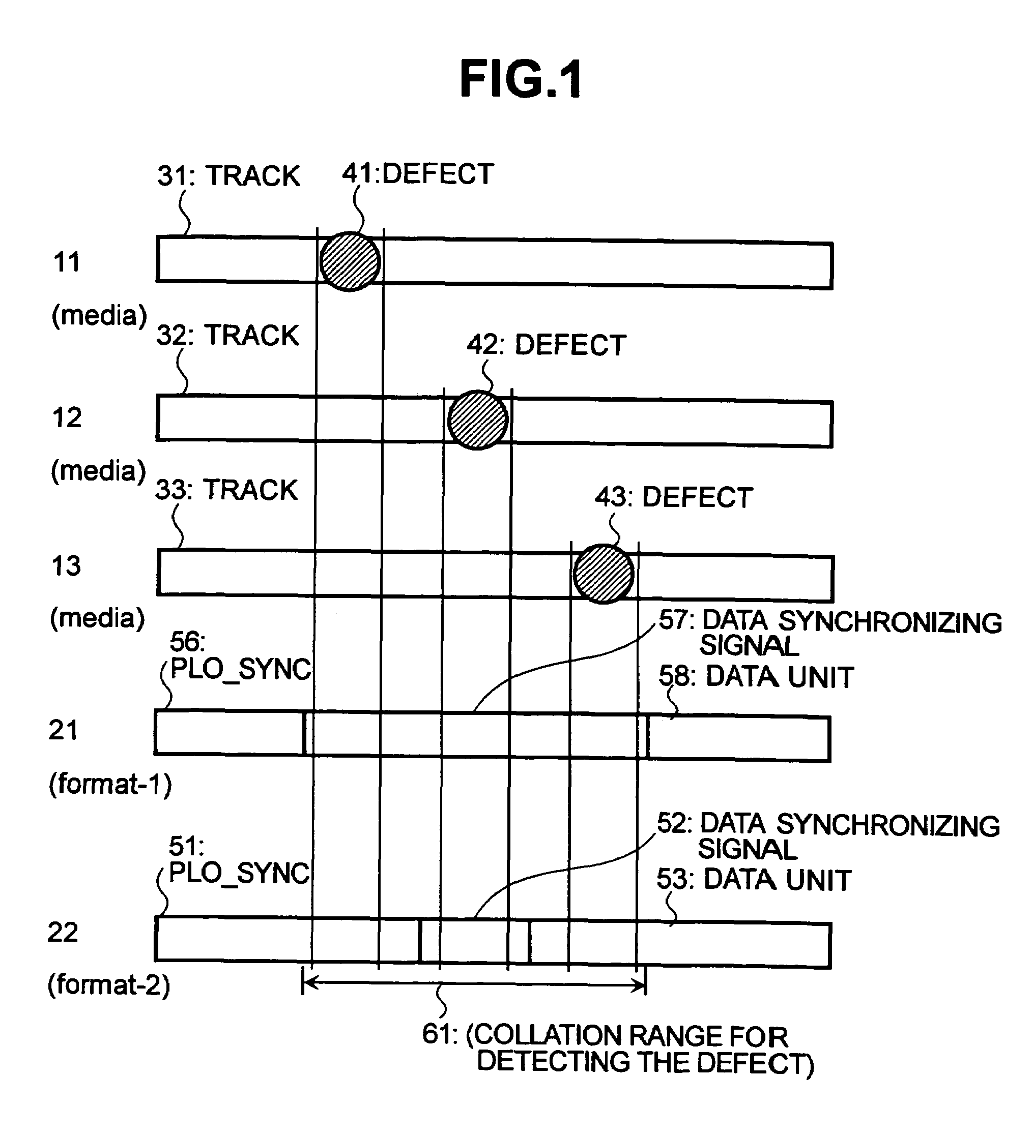
[0041]FIG. 1 illustrates the storing position of the storage medium and the format according to the invention. In an information storing / reproducing device using a disk-like storage medium such as a magnetic disk drive, information is stored in a region called track arranged in concentric on the disk-like storage medium. A storage medium 11 in FIG. 1 depicts a portion of the track in which information is stored on the recording medium. A track 31 has a defect 41 at an illustrated portion that is not suited for storing and reproducing information. A format in which information is stored on the track 31 is represented by a format 22. The format 22 includes a PLO-SYNC portion 51, a data-synchronizing signal portion 52, and a DATA portion 53. When the format 22 is stored on the track 31, the portion of the defect 41 comes into the region of PLO-SYNC 51. When the data are to be reproduced in the thus stored state, the defect 41 is drawn by the PLL that synchronizes the clocks and comes t...

second embodiment

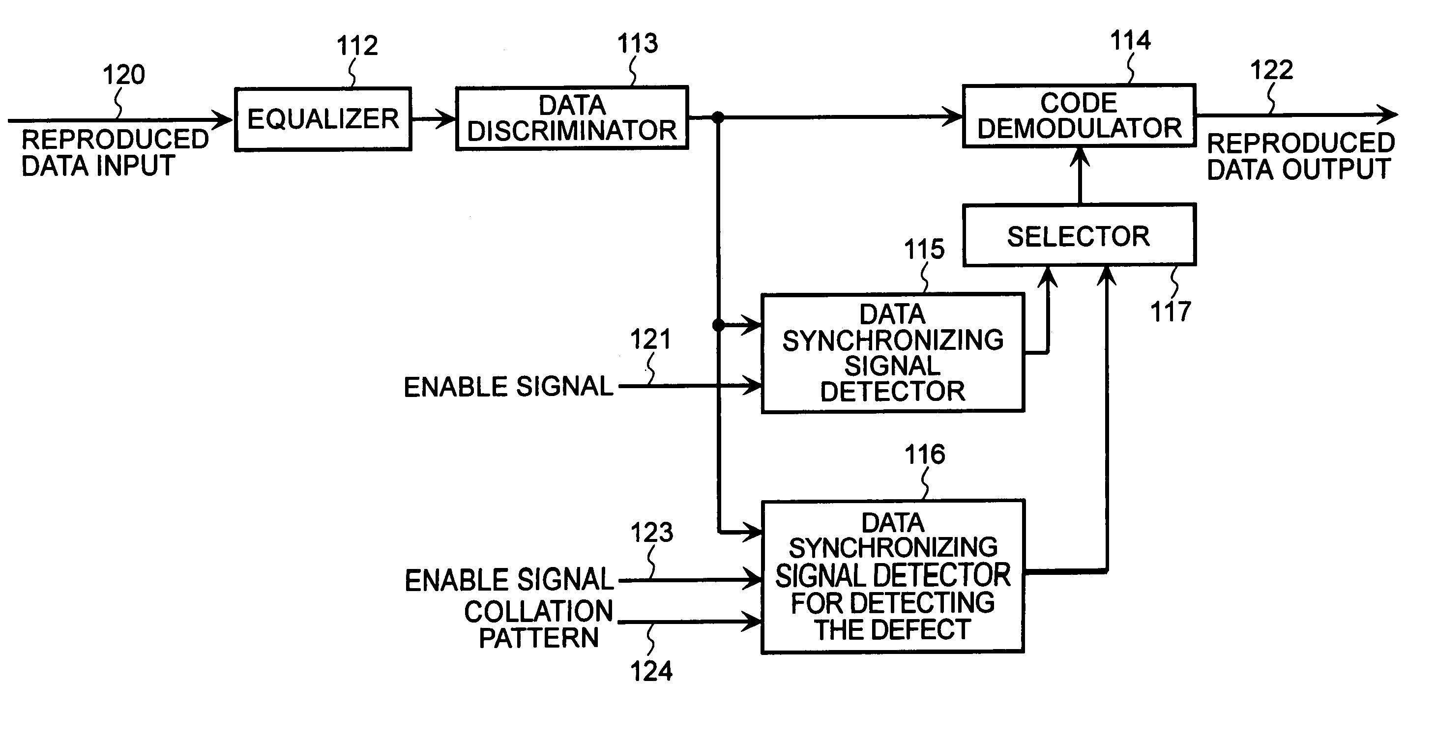
[0069]Next, described below with reference to FIG. 6 is the constitution of the defect detecting device according to the FIG. 6 is a diagram illustrating the constitution of the reproduction system inclusive of data-synchronizing signal detection means for the defect detecting device. Information constituted like the format 22 of FIG. 1 is reproduced, and is inputted to the equalizer 112 as a reproduced data input 120. The equalizer 112 equalizes the signals and outputs them. A data discriminator 113 receives the output from the equalizer, discriminates the data, and produces a result of data discrimination. The output of data discrimination is inputted into a selector 119, a delay unit 118, a data synchronizing signal detector 115 and to a data-synchronizing signal detector 125 for detecting defect. The data-synchronizing signal detector 115 is a data-synchronizing signal detection means which is used for normally reproducing the data, and receives an enable signal 121. If necessa...

third embodiment

[0072]The defect-detecting device according to the invention will be described next with reference to the drawings.

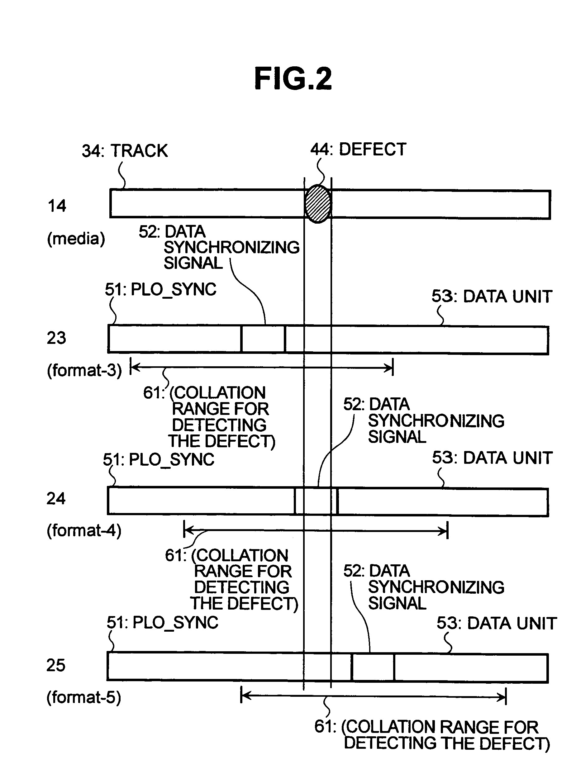
[0073]Like the second embodiment of the invention, the third embodiment of the invention uses the format 22 of the structure same as that of the case of normally reproducing the data of FIG. 1. The data-synchronizing signal, too, is detected in the same manner as the case of normally reproducing the data. Here, however, the presence of error is detected by conducting a separate pattern collation over a range represented by the collation range 61 for detecting the defect. In particular, the patterns are collated concerning the end portion of the PLO-SYNC 51, data-synchronizing signal 52 and head portion of the DATA portion 53. In this case, too, the defect is detected. Therefore, known data are used and are set as collation patterns. The collation range 61 for detecting the defect is set to be equal to the range of the data-synchronizing signal 52 for detecting the defec...


PUM


Abstract

In order to precisely detect latent defects where a data-synchronizing signal is to be stored despite changes in the rotation of an information storage medium, a region data detection is used during a defect detection mode that is longer in the back-and-forth direction than a data-synchronizing signal used during a normal operation mode. The data detection region may be increased by the amount of change in the rotation. Thus, latent defects that may, due to a change in the rotation of the storage medium, come into agreement with the position of a data-synchronizing signal utilized during a normal mode of operation may be reliably detected, maintaining a high precision by taking a change in the rotation of the storage medium into consideration.

Description

BACKGROUND OF THE INVENTION[0001]1. Field of the Invention[0002]This invention relates to technology for storing and reproducing information. More particularly, the invention relates to technology that can be effectively applied to a method of detecting defect in the information storage medium in the information storing / reproducing device, and to a defect detecting device.[0003]2. Description of the Related Art[0004]A general method of detecting defect will now be described with reference to a magnetic disk drive.[0005]The magnetic disk drive stores and reproduces information into, and from, a storage medium for each of the sectors that are unit storage regions. FIG. 15 is a diagram illustrating a sector format. Each sector includes a PLO-SYNC 51 for drawing a PLL (phase locked loop) for synchronizing the clocks, a data-synchronizing signal 52 for obtaining a demodulation timing signal of a code modulated by detecting a DATA start position, a DATA portion 53 for really storing and r...

Claims


Application Information

Patent Timeline
IPC IPC(8): G11B20/10G11B20/12G11B20/14G11B20/18G11B27/30G11B27/36
CPCG11B20/18G11B27/3027G11B27/36G11B2220/20G11B2220/2525
Inventor WATANABE, YOSHIJU
Owner HITACHI GLOBAL STORAGE TECH JAPAN LTD
Why Eureka
Try Eureka