Magnetic detector

a detector and magnetic field technology, applied in the field of magnetic detectors, can solve problems such as the generation of dispersion in the final output, and achieve the effects of reducing noise resistance, improving sn ratio, and improving noise resistan

Active Publication Date: 2005-12-20
MITSUBISHI ELECTRIC CORP
View PDF6 Cites 17 Cited by
  • Summary
  • Abstract
  • Description
  • Claims
  • Application Information

AI Technical Summary

Benefits of technology

[0008]In consideration of such points, an object of this invention is to provide a magnetic detector able to reduce the dispersion of characteristics due to the dispersion of the resistance value of the magnetic resistance segment, the dispersion of the temperature coefficient of the magnetic resistance segment, or the position dispersion generated at the assembly time, etc., and improve a noise resisting amount and obtain preferable detecting performance.
[0013]In accordance with the rotating detector of this invention, the SN ratio can be improved by setting the pitch P of the magnetic resistance segments at both ends constituting the magnetoelectric converting element, the size X of the magnet in the moving direction of the magnetic moving body, and the size Y of the magnet in the direction opposed to the magnetic moving body to a predetermined relation. Further, the dispersion of characteristics due to the dispersion of the magnetic resistance segment can be reduced and the noise resisting amount can be also improved and preferable detecting performance can be obtained.

Problems solved by technology

As its result, a problem exists in that dispersion is generated in the final output.

Method used


Image

  • Magnetic detector
  • Magnetic detector
  • Magnetic detector

Examples


embodiment mode 1

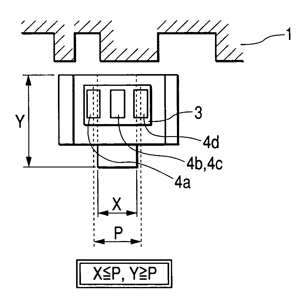
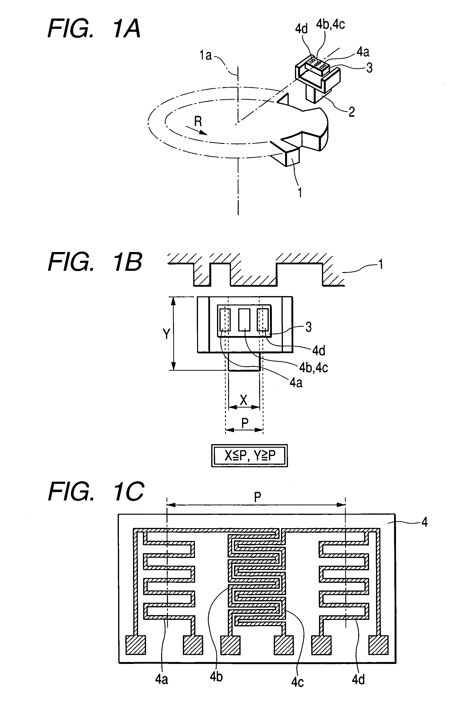
[0018]FIG. 1 is a constructional view showing a rotating detector of an embodiment mode 1 of this invention. FIG. 1A is a perspective view of the rotating detector. FIG. 1B is a top view of the rotating detector. FIG. 1C is a pattern view of a GMR element segment.

[0019]This rotating detector has a magnetic moving body 1 of a gear shape having a shape for changing a magnetic field, a magnet 2 and a signal processing circuit section 3. The magnet 2 is arranged so as to be opposed to the magnetic moving body 1, and is magnetized in the direction perpendicular to the direction opposed to the magnetic moving body 1, i.e., in the rotating axis direction 1a of the magnetic moving body 1. A magnetoelectric converting element 4 constructed by four GMR element segments 4a to 4d arranged at a predetermined pitch along the rotating direction of the magnetic moving body 1 is formed in the signal processing circuit section 3.

[0020]Each of these four GMR element segments 4a to 4d is formed by a fi...


PUM


Abstract

A magnetoelectric converting element is constructed by four or more magnetic resistance segments symmetrically arranged at a predetermined pitch with respect to the central line of a magnet perpendicular to the rotating direction of a magnetic moving body. The magnetizing direction of the magnet is set to the direction perpendicular to the direction opposed to the magnetic moving body. Further, 0.7P≦X≦P and P≦Y≦1.6P are set when the size of the magnet in the moving direction of the magnetic moving body is set to X and the size of the magnet in the direction opposed to the magnetic moving body is set to Y and the pitch of the magnetic resistance segments at both ends constituting the magnetoelectric converting element is set to P.

Description

BACKGROUND OF THE INVENTION[0001]1. Field of the Invention[0002]This invention relates to a magnetic detector able to detect the rotating position of a magnetic moving body by using a magnetoelectric converting element.[0003]2. Description of the Related Art[0004]As shown in patent literature 1, the conventional magnetic detector using the magnetoelectric converting element has a magnetic moving body having a shape for changing a magnetic field, a magnet, and a processing circuit section. The magnet is arranged so as to be opposed to the magnetic moving body, and is magnetized in the rotating axis direction of the magnetic moving body. In the processing circuit section, first to fourth magnetic resistance segments are integrally constructed and are arranged at a predetermined interval in the rotating direction of the magnetic moving body. The first and second magnetic resistance segments constitute a bridge circuit, and the third and fourth magnetic resistance segments constitute a ...

Claims


Application Information

Patent Timeline
Patent Type & Authority Patents(United States)
IPC IPC(8): G01B7/14G01B7/30G01D5/14G01D5/16G01P3/54
CPCG01D5/147
Inventor YOKOTANI, MASAHIROSHINJO, IZURU
Owner MITSUBISHI ELECTRIC CORP
Why Eureka
Try Eureka