Transceiver control with sleep mode operation

a technology of transceiver and sleep mode, applied in the field of wireless communication devices, can solve the problems of limiting the amount of time a device receiving the response must remain in the receiving mode, and limiting the amount of time a device can take to respond, so as to achieve no delay in the exchange of information, the effect of sufficient strength

Inactive Publication Date: 2005-12-20
TELXON INC
View PDF10 Cites 169 Cited by
  • Summary
  • Abstract
  • Description
  • Claims
  • Application Information

AI Technical Summary

Benefits of technology

[0015]Such control of the power applied to the receiver circuitry based on the RSSI signal or other properties of the incoming signal provides two distinct benefits. First, conservation of power is achieved by requiring that the receiver circuitry be fully powered only when a signal of sufficient strength and / or intelligibility is received. Secondly, system performance is optimized with respect to data exchange rates as a result of the mobile terminal receiver always being able to change quickly from a sleep mode to an active mode to receive information. Consequently, no delays in the exchange of information exist as compared to mobile terminals operating in a conventional power savings mode.
[0016]Additionally, the present invention relates specifically to a transceiver which begins to power up the transmitter as soon as it is determined that a packet being received requires a response. A control circuit within the transceiver processes the packet as it is received to determine whether the packet requires a response. If it is determined that a response is necessary, the control circuit provides a control signal to the transmitter to power up the transmitter from a sleep mode even before the entire packet has been received. The control circuit then continues to process the remainder of the packet as it is received while the transmitter powers up from the sleep mode. In this manner, the transmitter will become stabilized much earlier. Accordingly, the transceiver is able to respond more quickly than conventional devices and is thus able to increase response times and overall data exchange rates. Moreover, battery power of the transceiver is utilized more efficiently as compared to devices which must continuously maintain the transmitter in a fully powered mode.

Problems solved by technology

First, it speeds up data exchange between devices by limiting the amount of time a device can take to respond.
Secondly, it limits the amount of time a device receiving the response must remain in the receiving mode.
As mentioned above, since the transmitter and receiver oftentimes are connected to the same antenna, a device may miss information if it is transmitting information at the same time it could be receiving information.
During such time when a device is receiving information but not transmitting information, a fully powered transmitter can nevertheless consume a considerable amount of power.
An unfortunate consequence of placing the transmitter of a device into a sleep mode is that the data exchange rate will be reduced.
As a consequence, overall data exchange rate suffers.
Furthermore, given the strict SIFS time limitations typically in place, it is difficult for the transmitter to respond to a packet during the short period of SIFS time remaining after the transmitter has reached a fully powered state (i.e., stabilized).
Systems attempting to meet the aforementioned strict SIFS time limitations typically have higher probabilities of errors occurring in each transmission.
In addition, as higher spectral density modulation techniques are implemented (typically to increase data rate), more complex transmitter circuitry is utilized which requires even longer stabilization time.
Thus, even greater possibilities of transmission errors or slower data exchange rates exist.
Unfortunately, however, regardless of when a base station is prepared to communicate with the mobile terminal, the base station must buffer all information until such time when the mobile terminal indicates to the base station that its receiver is activated from the sleep mode to receive information.
The undesirable result of this power saving protocol is that, in exchange for the power conservation obtained via this mode, a substantial reduction in the data exchange rate results.
More specifically, since the mobile terminal receiver cannot receive information at all times there is a delay in the exchange of data.
Other conventional approaches for conserving power by placing the receiver into a sleeping mode suffer from similar drawbacks.
Again, however, the mobile terminal cannot receive information at all times. As a result, the data exchange rate is much lower than in the case where the mobile terminal is able to receive information at virtually any time.

Method used


Image

  • Transceiver control with sleep mode operation
  • Transceiver control with sleep mode operation
  • Transceiver control with sleep mode operation

Examples


Embodiment Construction

[0035]The present invention will now be described with reference to the drawings in which like reference numerals are used to refer to like elements throughout.

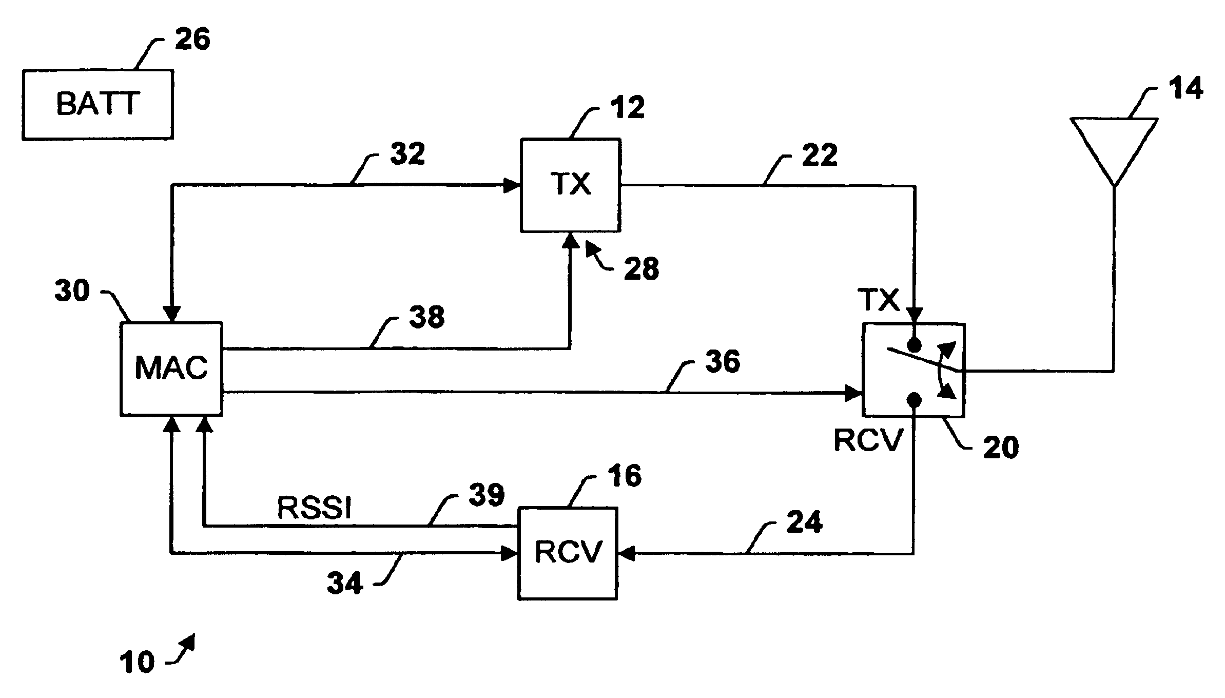
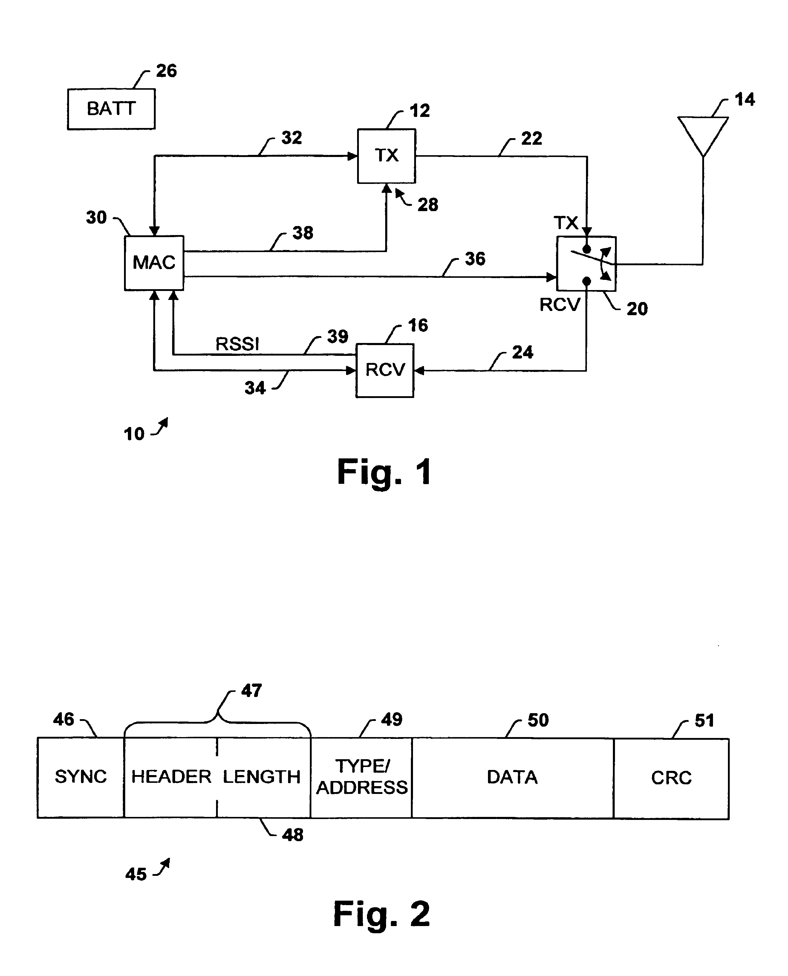
[0036]Referring initially to FIG. 1, a transceiver in accordance with the present invention is generally designated 10. The transceiver 10 includes a radio transmitter 12 for transmitting radio signals via an antenna 14. In addition, the transceiver 10 includes a radio receiver 16 for receiving radio signals via the antenna 14. An antenna switch 20 allows the transceiver 10 to transmit or receive signals depending on the position of the switch. When the switch 20 is in the transmit (TX) position, the antenna 14 is coupled to the output of the transmitter 12 via line 22 so that the transmitter 12 can transmit information. Alternatively, when the switch 20 is in the receive (RCV) position the antenna 14 is coupled to the input of the receiver 16 by way of line 24. The receiver 16 thereby receives information via the antenna 14....


PUM


Abstract

A transceiver which keeps circuitry associated with a receiver in a powered down state during periods when a Received Signal Strength Indicator (RSSI) indicates that a signal being received is below a pre-determined threshold level, and which begins to power up the transmitter as soon as it is determined that a packet being received requires a response. The RSSI signal represents the strength of any signal current being received, and if the RSSI signal falls below a given threshold level, digital circuitry associated with the back-end circuitry of the receiver system is disabled. If the RSSI signal rises above the threshold level, the digital circuitry of the receiver is enabled. A control circuit within the transceiver processes the packet as it is received to determine whether the packet requires a response. If it is determined that a response is necessary, the control circuit provides a control signal to the transmitter to power up the transmitter from a sleep mode even before the entire packet has been received and processed. The control circuit then continues to process the remainder of the packet as it is received while the transmitter powers up from the sleep mode. In this manner, the transmitter will become stabilized much earlier. Accordingly, the transceiver is able to respond more quickly than conventional devices and is thus able to increase response times and overall data exchange rates. Moreover, battery power of the transceiver is utilized more efficiently compared to devices which must continuously maintain the receiver and transmitter in fully powered modes.

Description

CROSS REFERENCE TO RELATED APPLICATION[0001]This application is a continuation-in-part of U.S. patent application Ser. No. 08 / 905,914, filed on Aug. 4, 1997, U.S. Pat. No. 5,800,110, which is a continuation of application Ser. No. 08 / 437,181, filed May 8, 1995, abandoned.TECHNICAL FIELD[0002]The present invention relates generally to wireless communication devices, and more particularly to transceivers having a receiver and / or transmitter which switches between a high power consumption mode and a low power consumption (or “sleep”) mode.BACKGROUND OF THE INVENTION[0003]In recent years, the use of wireless communication systems having mobile transceivers which communicate with a hardwired network, such as a local area network (LAN) or a wide area network (WAN), has become widespread. The mobile transceivers, commonly referred to as mobile terminals, may take one of several different forms. For instance, in retail stores hand-held scanning units may be used to allow for scanning invent...

Claims


Application Information

Patent Timeline
Patent Type & Authority Patents(United States)
IPC IPC(8): H04B1/16H04B7/00H04B7/005H04W52/02
CPCH04B1/1615H04W52/0245H04W52/028H04W52/04Y02B60/50Y02D30/70
Inventor MORELLI, DANIEL J.TROMPOWER, MICHAEL L.
Owner TELXON INC
Why Eureka
Try Eureka