Power factor improving converter and control method thereof

a converter and power factor technology, applied in the direction of electric variable regulation, process and machine control, instruments, etc., can solve the problems of reducing efficiency and increasing the loss of switching due to boosting, and achieve the effect of improving efficiency

Inactive Publication Date: 2005-12-27
SANKEN ELECTRIC CO LTD
View PDF8 Cites 35 Cited by
  • Summary
  • Abstract
  • Description
  • Claims
  • Application Information

AI Technical Summary

Benefits of technology

[0010]An object of the present invention is to provide a power factor improving converter and its control method that enables to improve efficiency.
[0035]The control section (106, 205, 305) may include an amplifier (323) that compares a signal level of an output voltage signal corresponding to an output voltage with a signal level of a predetermined reference signal to output a difference signal between both signal levels as a signal that controls the target level of the switching current; and an output voltage signal control circuit (331) that reduces a signal level of an output voltage signal to be supplied to the amplifier (323) in such a way to reduce the target level of the switching current of the switching element (Q11, Q21, Q31) when the value of the obtained parameter is compared with the setting value and the value of the obtained parameter exceeds the setting value.

Problems solved by technology

Particularly, when the output current on a secondary side is high, switching loss due to boosting is increased to reduce efficiency.

Method used


Image

  • Power factor improving converter and control method thereof
  • Power factor improving converter and control method thereof
  • Power factor improving converter and control method thereof

Examples


first embodiment

[0078][First Embodiment]

[0079]A power factor improving converter according to a first embodiment is one that obtains a boost quantity of an inductor as a parameter and controls a target level of a switching current according to the obtained boost quantity.

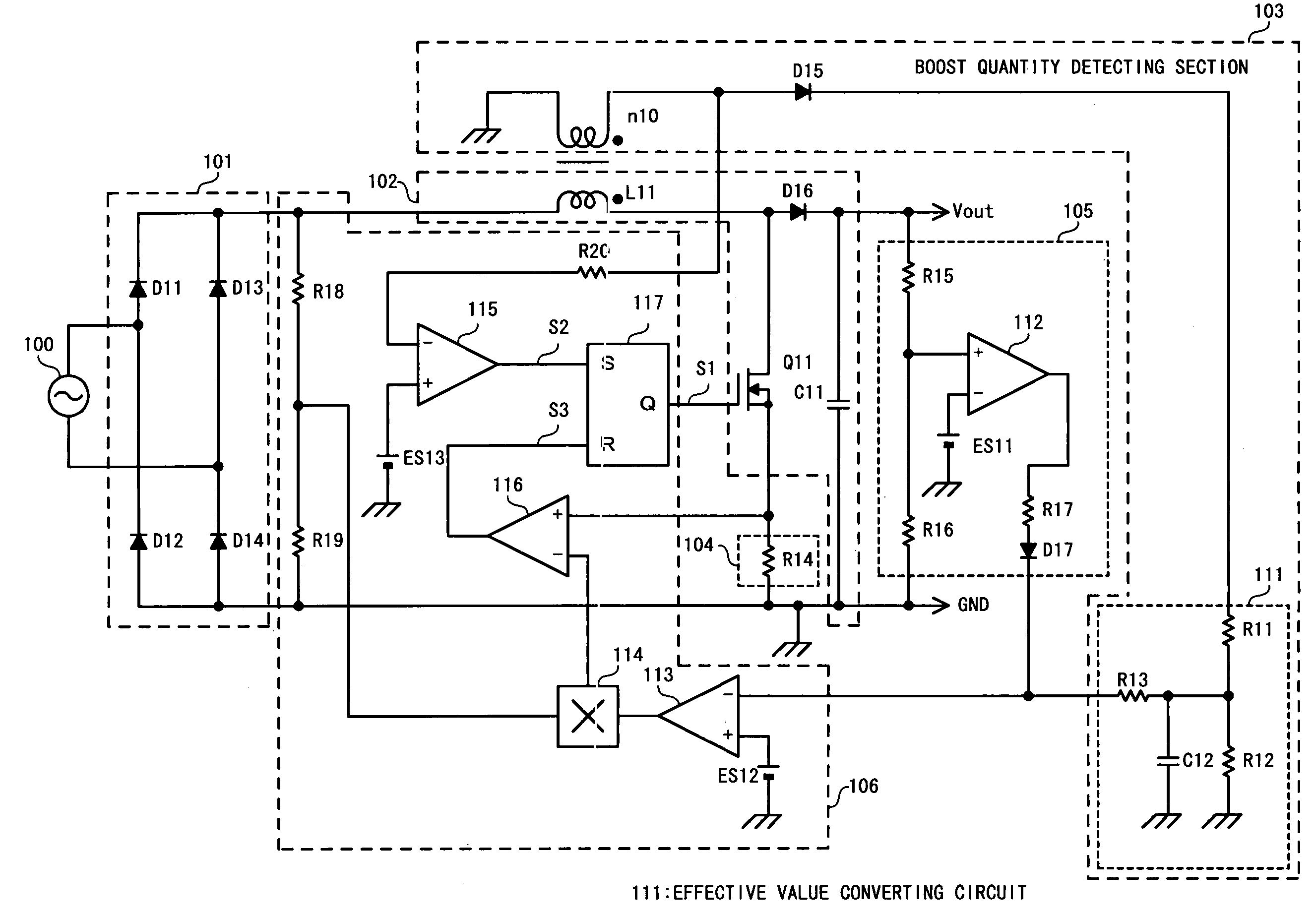
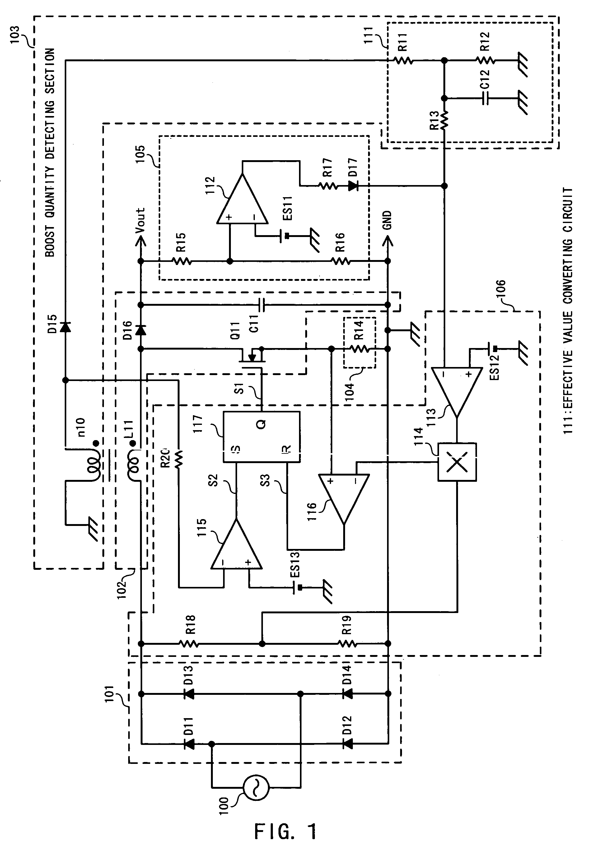
[0080]FIG. 1 illustrates a configuration of the power factor improving converter according to the first embodiment of the present invention.

[0081]The power factor improving converter according to the first embodiment of the present invention includes a rectifying section 101, a voltage converting section 102, a boost quantity detecting section 103, a switching current detecting section 104, an overvoltage protecting section 105, and a control section 106.

[0082]The rectifying section 101 is one that full-wave rectifies AC power supplied from an AC power source 100 to generate a ripple voltage and includes a bridge rectifying circuit having diodes D11 to D14.

[0083]A cathode of the diode D11 and a cathode of the diode D13 are connecte...

second embodiment

[0152][Second Embodiment]

[0153]A power factor improving converter according to a second embodiment is one that varies the reference voltage of the output voltage based on the effective value of the boost quantity to make it possible to perform control of the output voltage.

[0154]A configuration of the power factor improving converter according to the second embodiment is illustrated in FIG. 4.

[0155]The power factor improving converter according to the second embodiment includes a reference voltage generating circuit 121 in the control section 106.

[0156]The reference voltage generating circuit 121 is one that varies the reference voltage based on the output voltage of the effective value converting circuit 111 of the boost quantity detecting section 103 to supply the reference voltage ES12 to the +terminal of the operational amplifier 113.

[0157]The circuit configuration of the reference voltage generating circuit 121 is illustrated in FIG. 5.

[0158]The reference voltage generating cir...

third embodiment

[0168][Third Embodiment]

[0169]A power factor improving converter according to a third embodiment is one in which an upper limit value and a lower limit value are provided in the output voltage.

[0170]The power factor improving converter according to the third embodiment is configured, similar to the second embodiment illustrated in FIG. 4.

[0171]The power factor improving converter according to the third embodiment includes a reference voltage generating circuit 121 configured as illustrated in FIG. 7.

[0172]The reference voltage generating circuit 121 according to the third embodiment includes an amplitude limit circuit 124 in the reference voltage generating circuit 121 illustrated in FIG. 5.

[0173]The amplitude limit circuit 124 includes a resistor R25, a diode D18 and a Zener diode ZD11. One end of the resistor R25 is connected to the output terminal of the operational amplifier 122. The other end of the resistor R25 is connected to the +terminal of the operational amplifier 113.

[01...


PUM


Abstract

A boost quantity detecting section (103) detects a boost quantity of an inductor (L11). An operational amplifier (113) of a control section (106) compares the boost quantity detected by the boost quantity detecting section (103) with a reference voltage (ES12). When a supply voltage supplied from an AC power source (100) reduces and an output voltage is unchanged, the boost quantity detected by the boost quantity detecting section (103) increases. When a signal level of a boost quantity detection signal is higher than the reference voltage (ES12), a control section (106) reduces a target level of a switching current. The target level of the switching current decreases, so that the output voltage decreases and energy loss due to boosting reduces.

Description

TECHNICAL FIELD[0001]The present invention relates to a power factor improving converter and its method.BACKGROUND ART[0002]A power factor is expressed by power / (current×voltage) and called a phase difference between current and voltage of an alternating current (AC) circuit.[0003]In a capacitor input-type converter, a phase difference occurs when a waveform is distorted and a harmonic content is included in an input current. For this reason, there is used a power factor improving converter that controls a switching current to follow a waveform of a ripple voltage to improve a power factor without using a smoothing capacitor on a primary side where the ripple voltage is supplied.[0004]As the power factor improving converter, there is a current control type that controls the switching current in a critical mode.[0005]The power factor improving converter of the current control type includes a boost chopper circuit wherein a converter is configured using, for example, an inductor, a sw...

Claims


Application Information

Patent Timeline
Patent Type & Authority Patents(United States)
IPC IPC(8): H02M1/00H02M1/42H02M3/156
CPCH02M1/4225H02M3/1563H02M2001/0009H02M2001/4275Y02B70/126Y02B70/10Y02P80/10H02M1/0009H02M1/4275
Inventor FUKUMOTO, YUKINARIUSUI, HIROSHIMORITA, KOICHI
Owner SANKEN ELECTRIC CO LTD
Why Eureka
Try Eureka