Airframe structure-integrated capacitor

a capacitor and airframe technology, applied in the field can solve the problems of high energy density system, limited utility of modern day weapon concepts, and limited fielding/commercialization of large pulsed power,

Inactive Publication Date: 2006-01-03
THE UNITED STATES OF AMERICA AS REPRESETNED BY THE SEC OF THE AIR FORCE
View PDF8 Cites 26 Cited by
  • Summary
  • Abstract
  • Description
  • Claims
  • Application Information

AI Technical Summary

Benefits of technology

[0005]The present invention provides a space and weight saving electrical energy storage arrangement in which portions of an aircraft already needed for structural and aerodynamic purposes are enabled to function as significant electrical energy storing elements of the capacitor type.

Problems solved by technology

Several modern day weapon concepts, particularly airborne directed energy weapon programs of interest to the U.S. military, appear to be limited in utility by the existing developmental state of the energy storage electrical capacitor.
The relatively large mass and physical size of such capacitors due to their low joules per pound capability—limit the possible fielding / commercialization of large pulsed power, high energy density systems.

Method used


Image

  • Airframe structure-integrated capacitor
  • Airframe structure-integrated capacitor
  • Airframe structure-integrated capacitor

Examples


Embodiment Construction

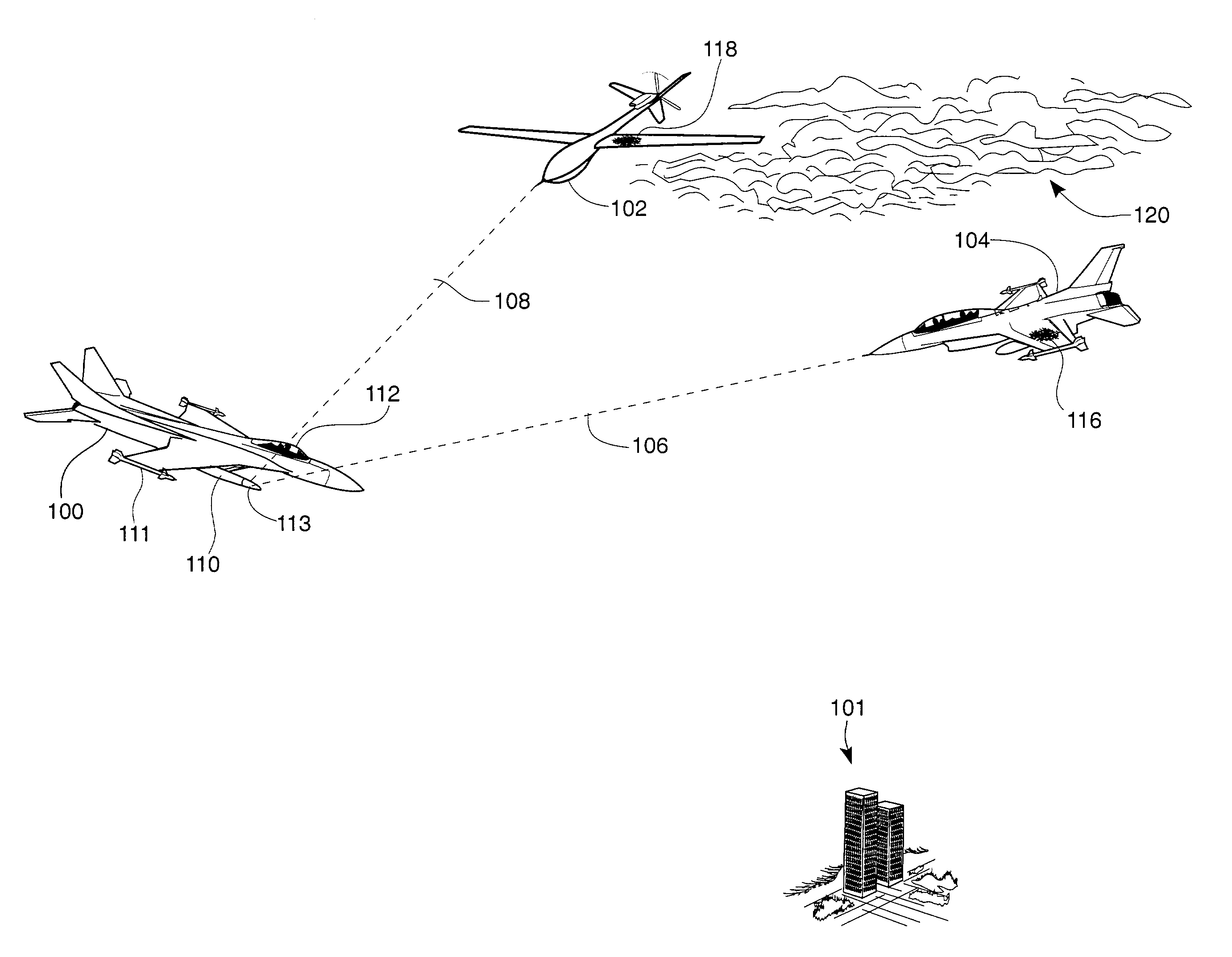
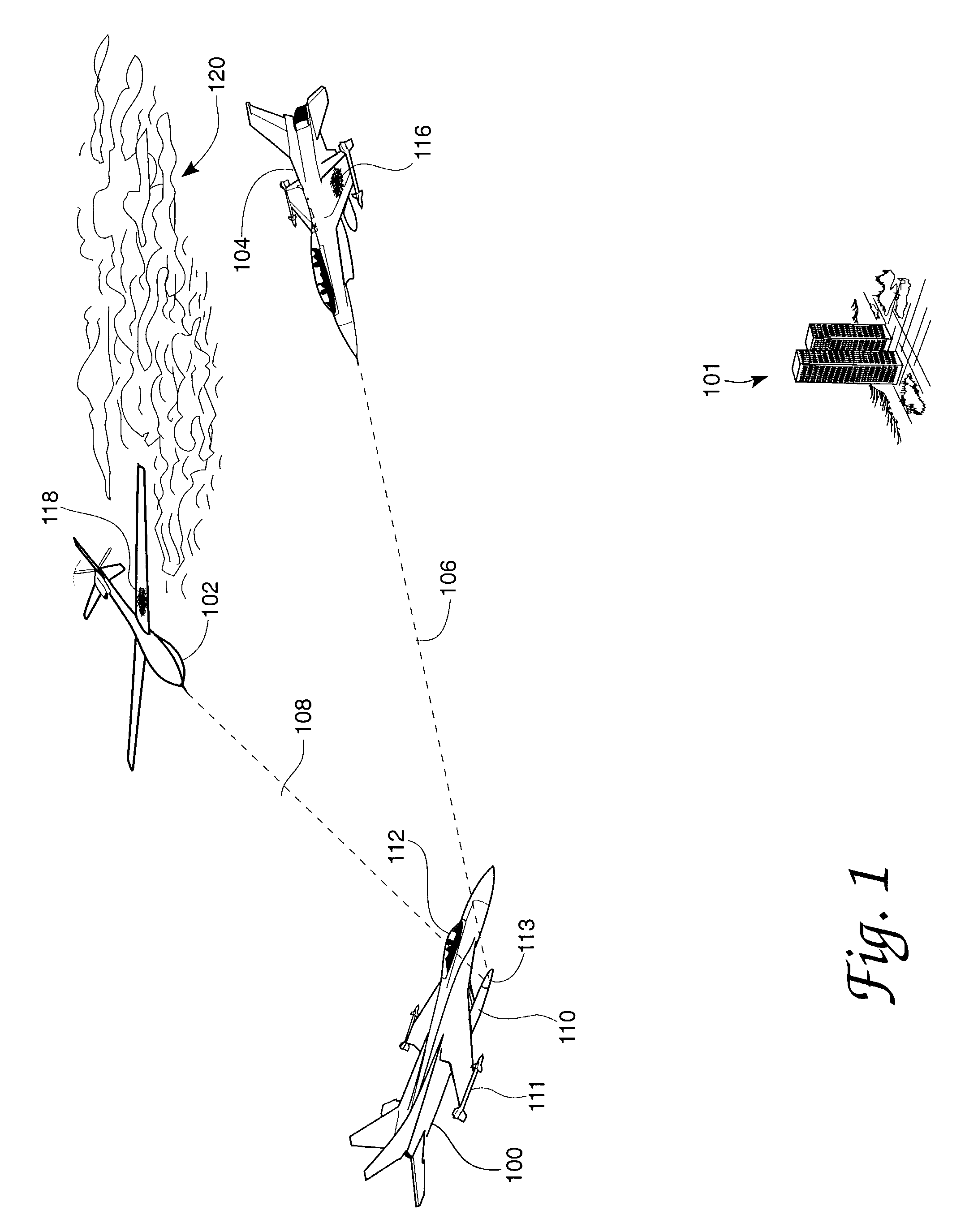
[0039]FIG. 1 in the drawings shows an aircraft combat scene in which an aircraft made according to the present invention may be useful. In the FIG. 1 drawing a hostile aircraft 100 has elected to approach a ground region 101 being protected by two aircraft made in accordance with the present invention. One of the protecting aircraft 104 is illustrated to be of the manned fighter type such as a special version of the F-16 fighter currently used by U.S. and friendly forces. The other of the protecting aircraft at 102 is illustrated to be of the unmanned type such as the Global Hawk unmanned surveillance / weapons carrier aircraft used in Afghanistan and other recent actions undertaken by the U.S. military; the aircraft 102 may have been “parked” or loitering in a cloud formation 120 for example. Each of the protecting aircraft 102 and 104 are represented in FIG. 1 as having established a boresight physical relationship with respect to the hostile aircraft 100, or some of its components ...


PUM


Abstract

An energy storage arrangement wherein electrical charge is stored in capacitor elements dispersed throughout, for example, surface structural components of an aircraft. The electrical capacitor elements may involve dielectric material-separated electrical plates comprising the aircraft skin or preferably may involve numerous wire-like cylindrical capacitor elements dispersed within the weaving of the hardened fabric materials used to fabricate the aircraft. Other elements of the aircraft including internal structure and divider members may also be included in the energy storage function. Pulsed use of the stored energy in, for example, directed energy weapons devices are a contemplated application of the invention. The invention may be viewed as a combined employment of aircraft components in both structural and energy storing functions thus enabling a reduction in aircraft payload utilization and space consumption.

Description

CLAIM OF PRIORITY[0001]This application claims the benefit of U.S. Provisional Application No. 60 / 279,532, filed Mar. 28, 2001.RIGHTS OF THE GOVERNMENT[0002]The invention described herein may be manufactured and used by or for the Government of the United States for all governmental purposes without the payment of any royalty.BACKGROUND OF THE INVENTION[0003]Several modern day weapon concepts, particularly airborne directed energy weapon programs of interest to the U.S. military, appear to be limited in utility by the existing developmental state of the energy storage electrical capacitor. The relatively large mass and physical size of such capacitors due to their low joules per pound capability—limit the possible fielding / commercialization of large pulsed power, high energy density systems. The present invention is focused on one way in which these limitations may be overcome through an unusual and at first blush radical revisiting of the aircraft materials and aircraft structures ...

Claims


Application Information

Patent Timeline
Patent Type & Authority Patents(United States)
IPC IPC(8): B64D45/02
CPCB64D27/24H01G11/40H01G4/203H01G11/32Y02T50/44Y02T50/64Y02E60/13Y02T50/60Y02T50/40
Inventor BARON, WILLIAMBLAIR, MAXWELLFRIES-CARR, SANDRA
Owner THE UNITED STATES OF AMERICA AS REPRESETNED BY THE SEC OF THE AIR FORCE
Why Eureka
Try Eureka