Micromixer

a micro-mixer and mixer technology, applied in the field of micro-mixers, can solve the problems of limited use of single mixers for large-scale chemical production and limited throughput, and achieve the effects of increasing the ratio of mixing zone area, increasing throughput per surface area, and reducing the percentage of unutilized surface area

Inactive Publication Date: 2006-01-03
IMM INST FUR MIKROTECHNIK GMBH
View PDF11 Cites 14 Cited by
  • Summary
  • Abstract
  • Description
  • Claims
  • Application Information

AI Technical Summary

Benefits of technology

[0011]There are two preferred embodiments of the inventive micromixer. Similar to the single mixer, the one embodiment has two feeding chambers, each of which has parallel main channels that intermesh in a comb-like manner, however. Branching off of each main channel are digital channels which likewise intermesh in a comb-like manner and form the mixing zones. This configuration increases both the number of mixing zones per mixer cell and the ratio of the surface area of the mixing zones relative to the total surface area of the mixer cell, and thus the throughput per surface are. The corresponding discharge plate has a multitude of parallel ports whose number is equal to the number of mixing zones.
[0013]This micromixer makes it possible to integrate two or more such mixers into a micromixer system. This is done by arranging one micromixer over the other and configuring the ports for feeding the reactants and discharging the products such that the product of the one micromixer is fed to the other micromixer as the second reactant. This makes it possible to produce products whose reactions occur in two or more stages.
[0017]In the second preferred embodiment of the inventive micromixer, mixing zones are arranged on all sides of the feeding chambers in the plane of the plates. Only those feeding chambers at the edge of the plane of the plates have mixing zones on only one or two sides. This increases the ratio of mixing zone area to mixer cell area and thus increases the throughput per surface area. The object of the invention is to arrange as many mixer cells as possible on the mixing plate. It is advantageous for the mixing plate to have 10 or more mixer cells per square centimeter.
[0018]It is advantageous if the feeding chambers are arranged according to the reactants in rows and / or columns in an alternating pattern. This further reduces the percentage of unutilized surface area. It is particularly advantageous if the feeding chambers are arranged in 4 or more rows and in 4 or more columns.

Problems solved by technology

A significant disadvantage of this single mixer is that its throughput is very limited.
Because of this low throughput, use of the single mixer for large-scale chemical production is limited.

Method used


Image

  • Micromixer
  • Micromixer
  • Micromixer

Examples


first embodiment

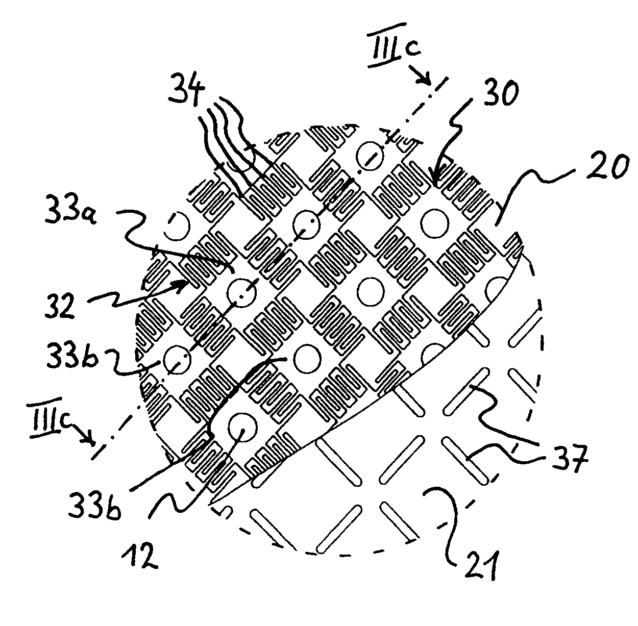
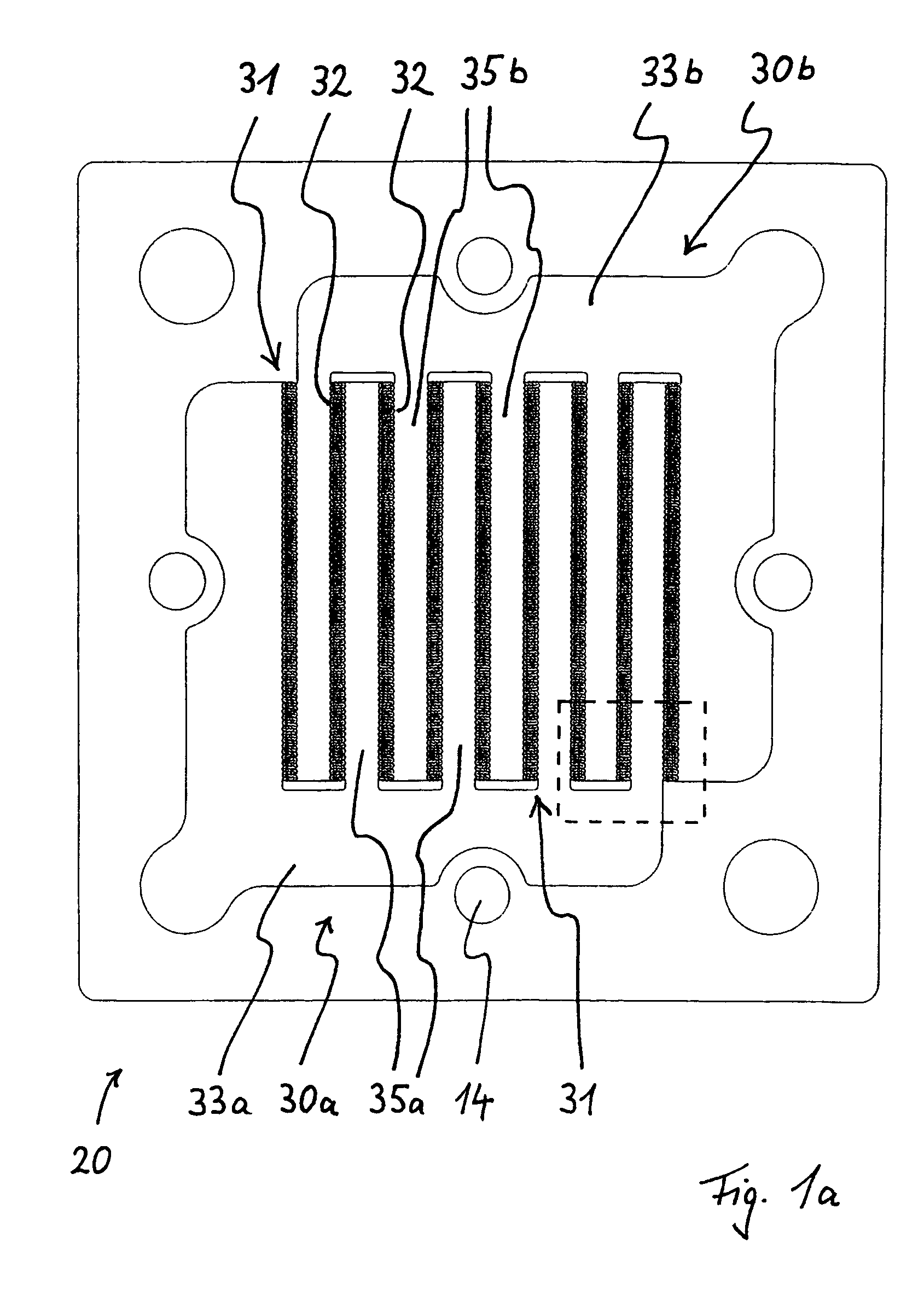
[0041]FIG. 1a shows a mixing plate 20. This mixing plate 20 has two feeding chambers 33a and 33b for the reactants A,B. Both feeding chambers 33a,b branch into four primary channels 35a,b. Microstructures 31 defining the mixing zones 32 between the main channels 35 for the reactants A and B are located on both sides along the main channels 35a,b. The main channels 35a,b intermesh in a comb-like manner. The feeding chambers 33a,b together with the mixing zones 32 each form a mixer cell 30a and 30b.

[0042]The mixing plate 20 also has recesses 14 by means of which the individual plates comprising the micromixer are screwed together.

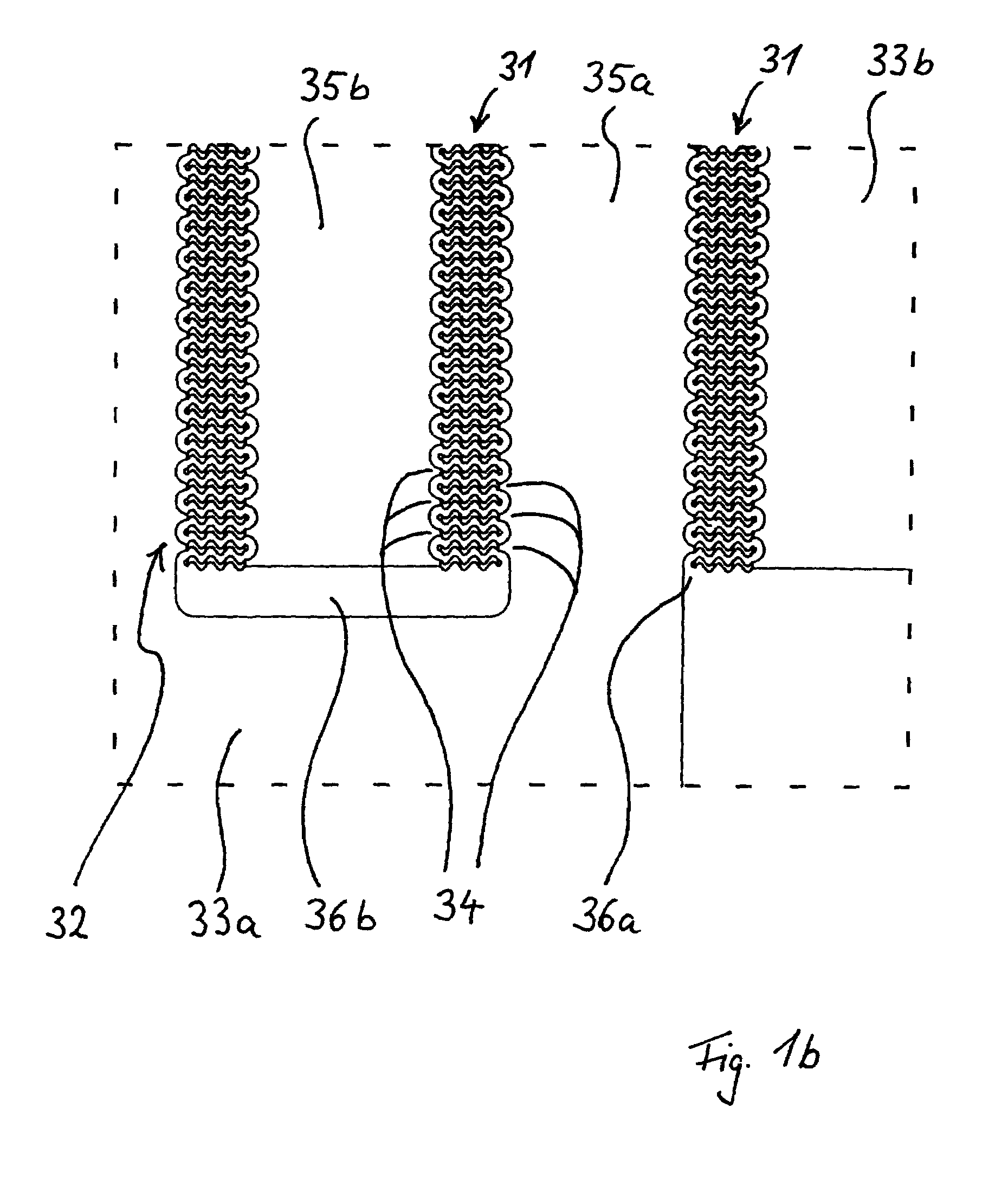
[0043]FIG. 1b is an enlarged view of that section of FIG. 1a marked with a broken line. One can see that digital channels 34 branch off from the main channels 35a,b. These digital channels are separated from one another by microstructures in the form of thin walls 36a. These walls 36a are corrugated and meandering to increase their mechanical stability. This...

second embodiment

[0060]FIG. 8 shows a second embodiment for the integration of a heat exchanger. In this embodiment, the product is again heated or cooled. The discharge plate comprises two individual plates 21a and 21b. These are arranged parallel to and at some distance from one another to form a chamber 40 for holding a heating medium or coolant. Both individual plates 21a and 21b are provided with discharge ports 37. The product is transported from one side of the cover plate [sic]21 to the other by means of flattened hollow bodies 41a arranged in the ports to form a connection from one side of the discharge plate 21 to the other.

third embodiment

[0061]FIG. 9 shows a third embodiment for heating or cooling the medium. The discharge plate 21 is again a two-piece construction, with an upper slotted plate 21a and a very much thicker lower slotted plate 21b. In addition to the ports 37, the lower, thicker plate 21b also has open-ended slots 42 for holding the coolant or heating medium which extend perpendicular to the ports 37 for the product. It is advantageous if a material with good thermoconducting properties is used for the manufacture of the lower plate 21b.

[0062]In some cases, it can also be desirable to preheat or cool the reactants. An embodiment enabling this is shown in FIG. 10. This is a micromixer with storage chambers 57a,b for the supply of reactants comprising two additional plates 22, 23. A third additional plate 24 is arranged between the first additional plate 22 and the mixing plate 20. This creates an additional chamber 40 between the mixing plate 20 and the third additional plate 24, in which chamber 40 a ...


PUM

PropertyMeasurementUnit
heightaaaaaaaaaa
heightaaaaaaaaaa
heightaaaaaaaaaa

Abstract

Known static micromixers that work according to the principle of multilamination allow for a rapid mixing by diffusion. The invention provides a means for substantially increasing the throughput of known micromixers. To this end, the inventive micromixer for mixing two or more reactants comprises microstructures that define mixer cells. Each of said mixer cells is provided with a feeding chamber which adjoins at least two groups of digital channels. Said channels intermesh with the digital channels of the groups adjoining the feeding channels in a comb-like manner, thereby producing mixing zones]. Outlet ports are located above said mixing zones, said outlet ports extending perpendicularly to the digital channels and discharging the product. The inventive micromixer is especially useful for the large-scale production of mixtures, dispersions and emulsions.

Description

FIELD OF THE INVENTION[0001]The invention relates to a micromixer for mixing at least two reactants having penetrations for the supply of the reactants and discharge of the product, having at least one mixing plate with microstructures that define mixer cells, each of said mixer cells having a feeding chamber which adjoins at least one group of digital channels which intermesh in a comb-like manner with the digital channels of a group from the adjoining feeding chamber; and having a discharge plate arranged on the mixing plate, said discharge plate having an outlet port above each mixing zone, said outlet port extending perpendicularly to the digital channels.BACKGROUND OF THE INVENTION[0002]Although microfluid components were developed years ago for analytical applications, microengineering techniques have only recently been applied to the development of equipment for chemical synthesis, so-called microreactors. Principle components of such microreactors are mixers and heat exchang...

Claims


Application Information

Patent Timeline
Patent Type & Authority Patents(United States)
IPC IPC(8): G01N33/48B01F15/00B01F5/06B01F13/00H04B7/26
CPCH04B7/26H04W28/22H04W28/24B01J2219/00783B01J2219/00891B01J2219/00995B01F25/422B01F25/4323B01F33/3012B01F33/3039
Inventor EHRFELD, WOLFGANGMICHEL, FRANKLOHF, ASTRIDGRAEFF, VOLKER
Owner IMM INST FUR MIKROTECHNIK GMBH
Why Eureka
Try Eureka