Indirect x-ray image detector for radiology

a detector and x-ray technology, applied in the field of indirect x-ray image detectors, can solve the problems of limiting the field of use of the array of scintillators, high cost and poor resolution, and difficult task of building an array of scintillators

Inactive Publication Date: 2006-01-03
ANALOGIC CANADA
View PDF14 Cites 10 Cited by
  • Summary
  • Abstract
  • Description
  • Claims
  • Application Information

AI Technical Summary

Benefits of technology

[0012]It is the object of the present invention to provide an improvement to the known systems by replacing the array of photodiodes or other photosensors used in the prior art by a photoreceptor formed of a uniform thin layer of photosensitive selenium having a multilayer structure, which leads to many important advantages.
[0013]A further object of the invention is to have the photoreceptor multilayer structure and the scintillator enclosed in a housing providing environmental, electric and mechanical protection.
[0017]It is preferable to enclose the selenium photosensitive multilayer photoreceptor and the scintillator within a suitable housing providing environmental, electrical and mechanical protection.
[0025]According to this invention, the role of the selenium multilayer is two-fold. Firstly, it acts as the light absorber layer thereby converting the incident energy into electrical charges proportional to the intensity level of the incident radiation. Secondly, it acts as the charge transport layer whereby the generated carriers are transported under the effect of an applied electric field to the underlying pixelated electrode. The thickness of the selenium multilayer is much less than the width of a pixel electrode so that in association with the direction of the electric field and the high intrinsic resistance of selenium, the lateral spread of charge is minimized.
[0028]The selenium multilayer is operated under an electric field (5 to 50 V / μm) having a gain of close to 1, with no avalanche multiplication. This allows the detector to operate under very high dose rates without having to saturate the output amplifiers.

Problems solved by technology

Also, the construction of an array of scintillators is a complex and difficult task which has not achieved widespread application.
Such prior art devices present a number of disadvantages in terms of high cost and poor resolution.
Also, they may be operated only by application of either high voltage or low voltage, thereby restricting their field of use.

Method used


Image

  • Indirect x-ray image detector for radiology
  • Indirect x-ray image detector for radiology
  • Indirect x-ray image detector for radiology

Examples


Embodiment Construction

[0034]In the Figures, the same elements are identified by the same reference numbers.

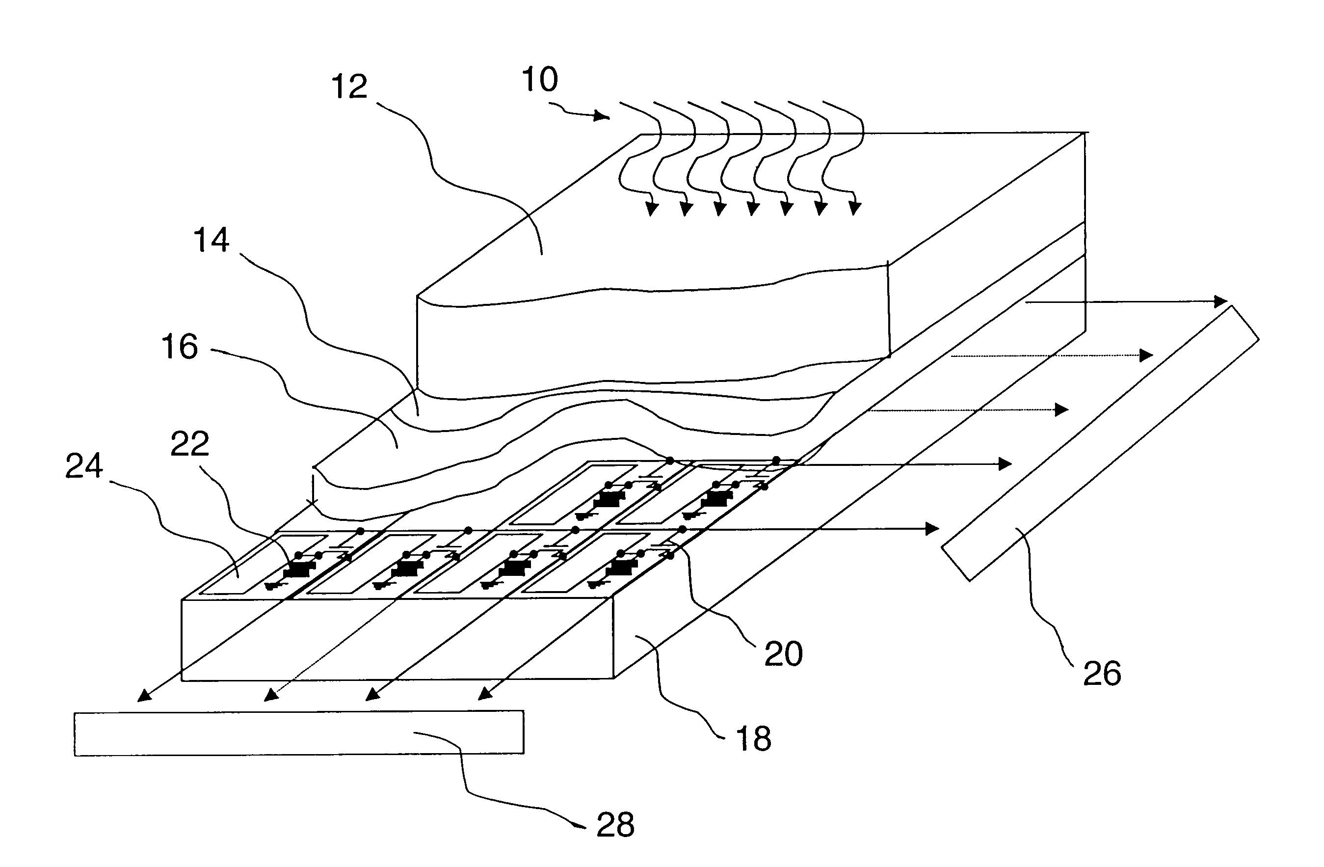
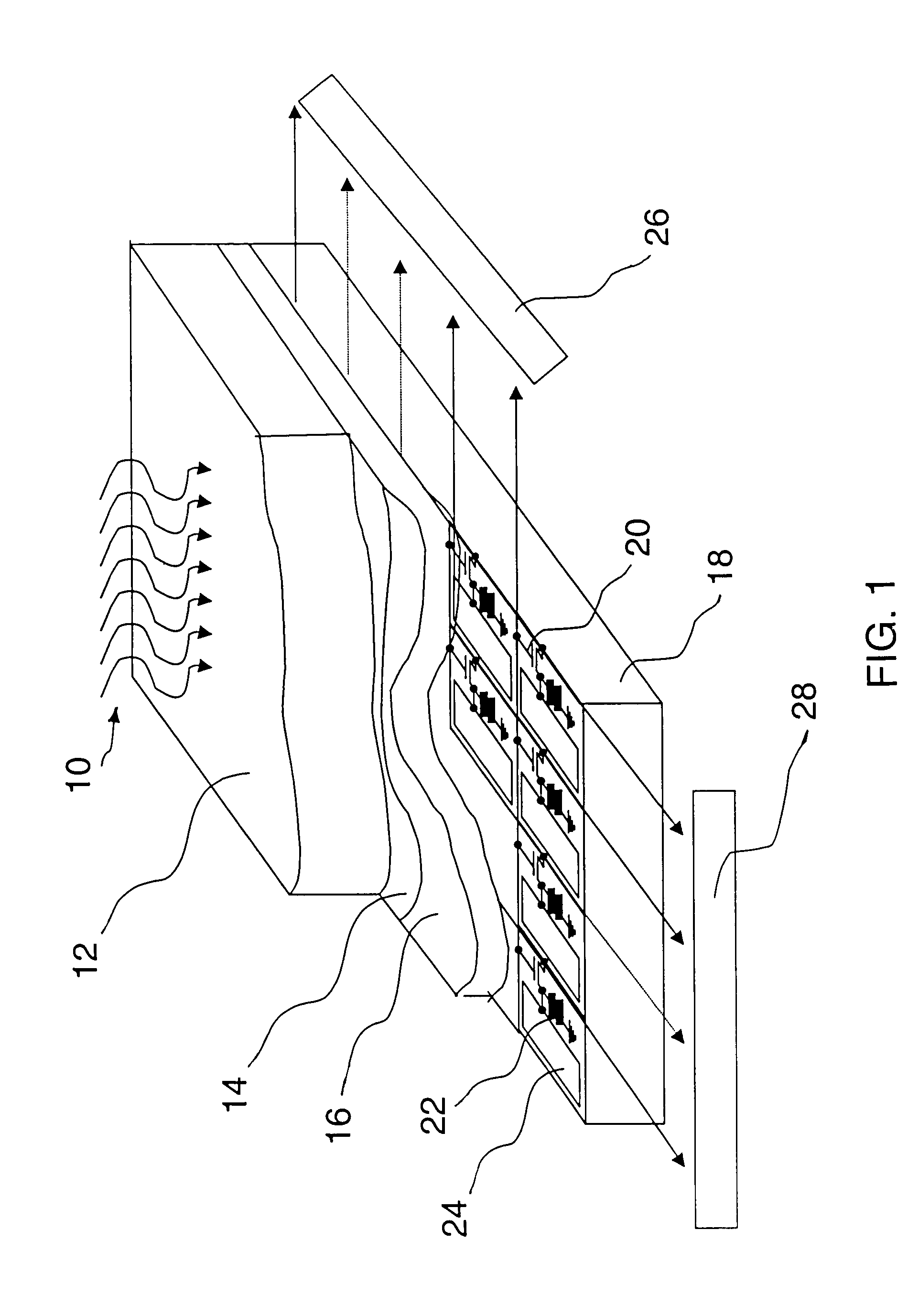
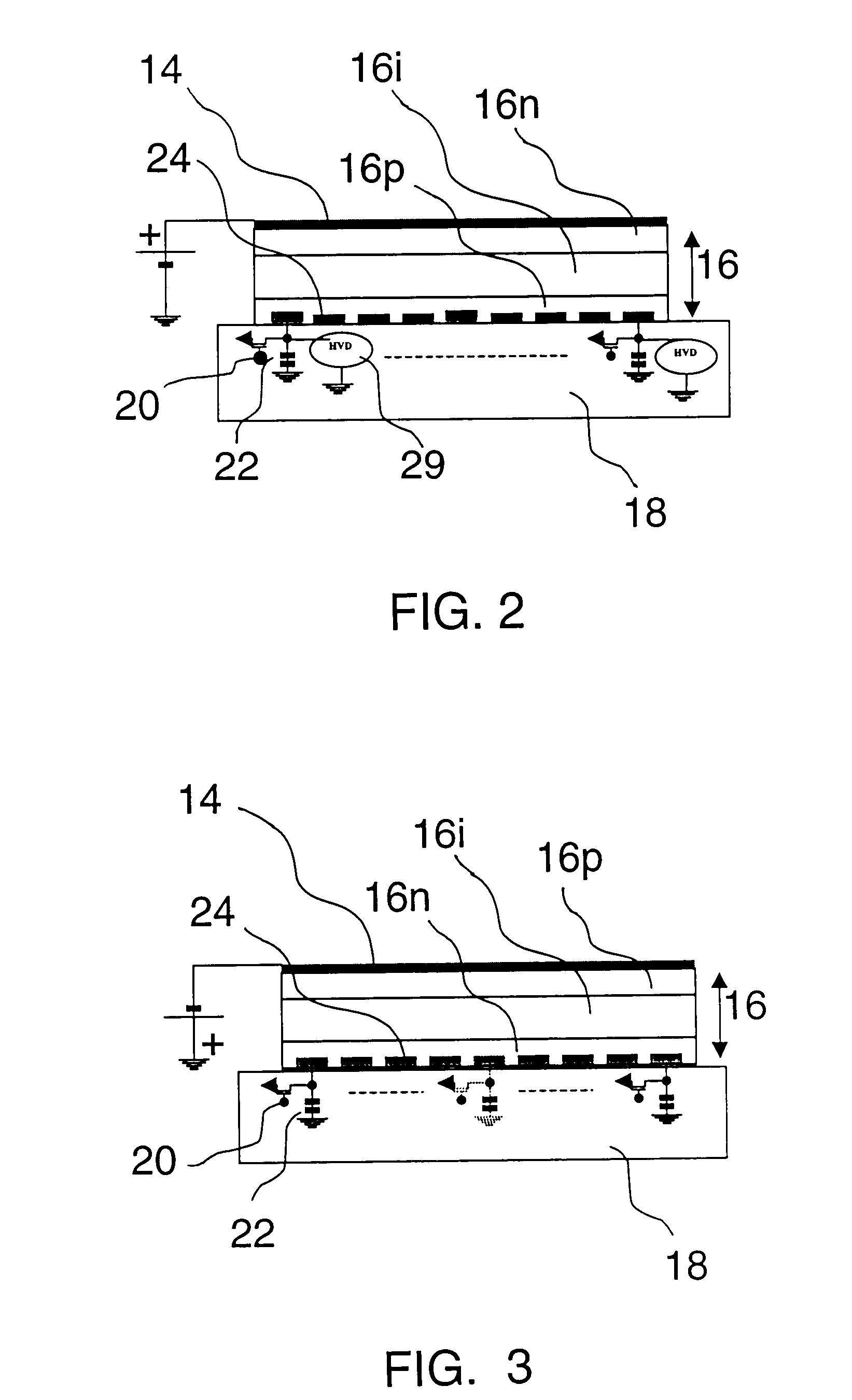
[0035]FIG. 1 illustrates an embodiment of the present invention wherein an x-ray beam 10 is directed onto the x-ray conversion scintillator 12 which, for example, may be made of CsI. Such scintillator is typically 300–500 μm thick and it absorbs about 80%–90% of incoming radiation while converting x-rays into light. Under the scintillator 12, there is provided a light transparent top biasing electrode 14 which can be made of materials such as ITO. Under this biasing electrode 14, the present invention provides a co-planar thin (e.g. 5–20 μm) layer of photosensitive selenium based photoreceptor 16 having a multilayer structure which converts light into electrical charges. This photosensitive layer 16 is deposited onto an active matrix substrate 18 comprising arrays of TFT switches 20, storage capacitors 22 and conduction pads 24. Such TFTs may also be replaced by switching diodes (not shown).

[0036]Th...


PUM


Abstract

An x-ray image detector suitable for radiology has an active matrix substrate with scanning and read-out circuits. Over this active matrix substrate, which can be a two dimensional array of TFTs associated with a storage capacitance, there is deposited a photoreceptor made of a thin layer of amorphous selenium based multilayer structure. The photoreceptor is covered with a light-transparent electrode on top of which there is provided a scintillator. The indices of refraction of the scintillator and of the selenium based multilayer may be matched with the use of the biasing electrode.

Description

BACKGROUND OF THE INVENTION[0001]1. Field of the Invention[0002]This invention relates to an indirect x-ray image detector suitable for radiology. The term “indirect” means that the x-rays are not directly converted into electrical charges, but rather they are first converted into light using a scintillator, and then light is converted into electrical charges by appropriate means. More particularly, this invention relates to an x-ray detector where the usual array of pixelated photodiodes used to convert light into electrical charges, is replaced by a photoreceptor formed of a thin uniform layer of photosensitive selenium having a multilayer structure.[0003]2. Description of the Prior Art[0004]It is well known to produce indirect x-ray image detectors based on a system comprising a thin film transistor (TFT) matrix deposited on a glass substrate and a corresponding array of photodiodes with an inherent capacitor, as well as an electrode connected to the source of the TFT. The photod...

Claims


Application Information

Patent Timeline
Patent Type & Authority Patents(United States)
IPC IPC(8): G01T1/20A61B6/00H01L27/146
CPCH01L27/14658
Inventor ROUGEOT, HENRI M.JEAN, ALAINMANI, HABIBSHUKRI, ZIAD AZIZ
Owner ANALOGIC CANADA
Why Eureka
Try Eureka