Circuit system for discharging a buffer capacitor used for supplying high voltage to a control unit, in particular a control unit for actuating a piezoelectric output stage

Inactive Publication Date: 2006-01-03
ROBERT BOSCH GMBH
View PDF22 Cites 27 Cited by
  • Summary
  • Abstract
  • Description
  • Claims
  • Application Information

AI Technical Summary

Benefits of technology

[0003]According to an exemplary circuit system of the present invention, electronic switching elements may be provided to permit discharge and prevent recharge of a high-voltage buffer capacitor of the piezoelectric output stage after the control unit is separated from the piezoelectric element via disconnection of the cable harness plug-in connector from the control unit plug-in connector or after the control unit is switched off.
[0004]In an exemplary embodiment of the present invention, electronic switching elements may be associated with the buffer capacitor inside the circuit system. For example, npn-switching bipolar transistors or MOSFET transistors across which a base-emitter voltage may be established after the cable harness plug-in connecto

Problems solved by technology

This circuit system may represent a safety cutoff for the supply of high vol

Method used


Image

  • Circuit system for discharging a buffer capacitor used for supplying high voltage to a control unit, in particular a control unit for actuating a piezoelectric output stage
  • Circuit system for discharging a buffer capacitor used for supplying high voltage to a control unit, in particular a control unit for actuating a piezoelectric output stage
  • Circuit system for discharging a buffer capacitor used for supplying high voltage to a control unit, in particular a control unit for actuating a piezoelectric output stage

Examples


Embodiment Construction

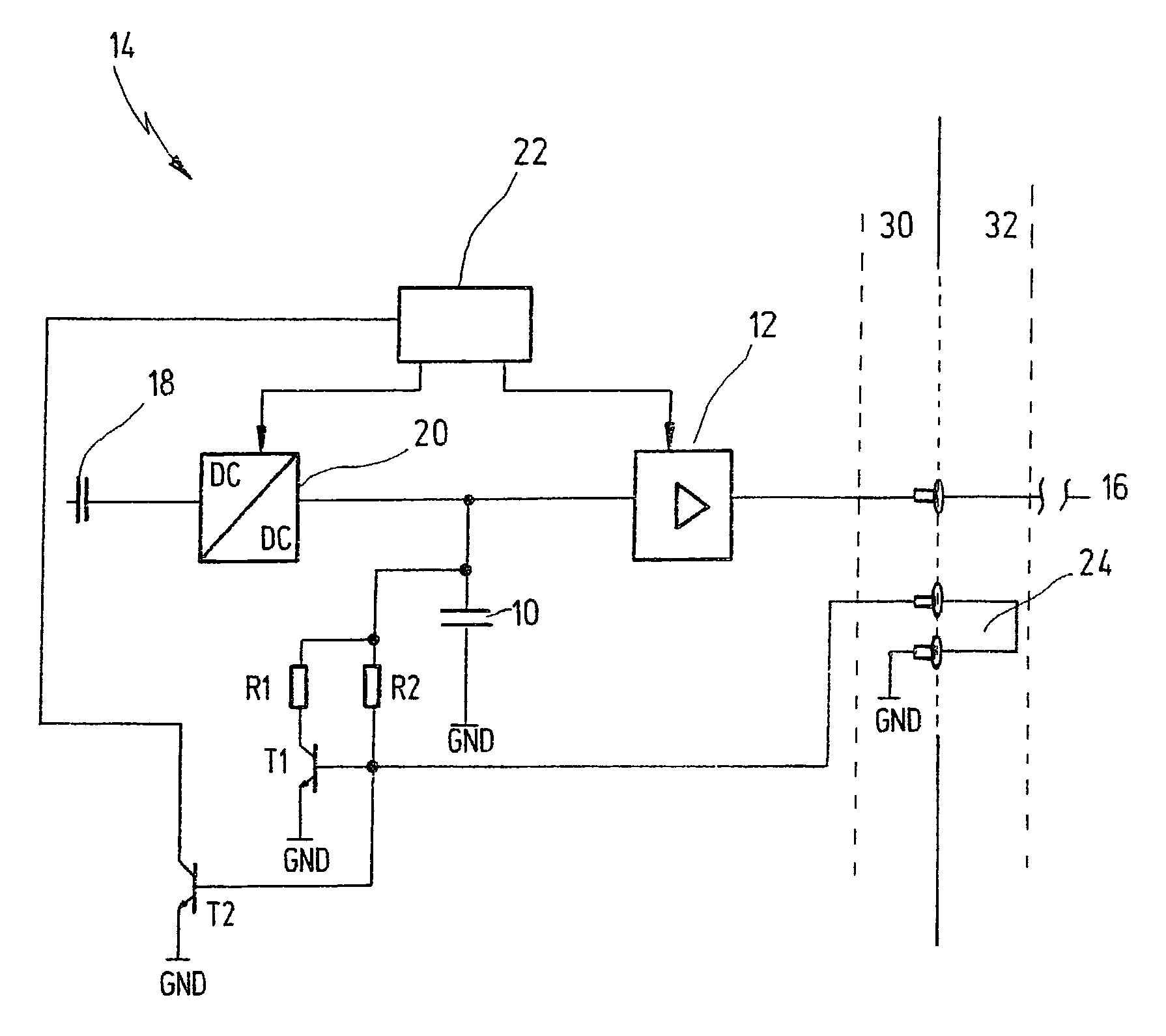
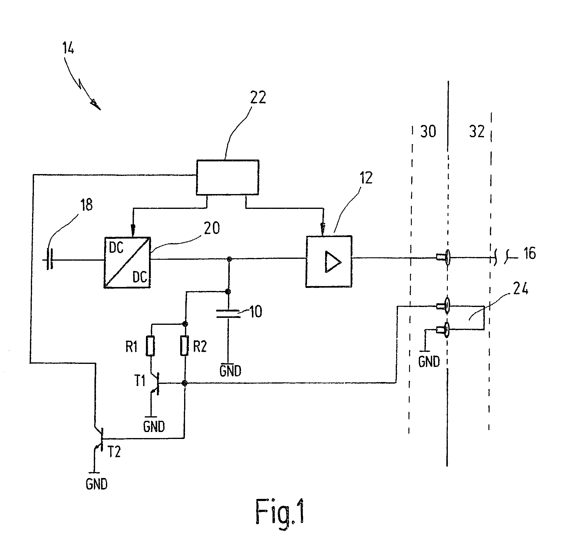
[0008]FIG. 1 shows a buffer capacitor 10 which is supplied with high voltage from a voltage source 18 via a direct current converter 20. Buffer capacitor 10 is used in a control unit 14 for supplying high voltage to a piezoelectric output stage 12. Direct current converter 20 and piezoelectric output stage 12 are controlled by a triggering device 22. Piezoelectric elements 16 are connected to piezoelectric output stage 12 via a control unit plug-in connector 30 and a cable harness plug-in connector 32. On the high-voltage side, a resistor R1 and a resistor R2 as well as electronic switching elements T1 and T2 are associated with buffer capacitor 10. Electronic switching elements T1 and T2 may be, for example, npn-switching bipolar transistors or MOSFET transistors. The bases of transistors T1 and T2 are connected to resistor R2 and to ground via a cable harness bridge 24 in control unit plug-in connector / cable harness plug-in connector 30, 32. The collector of electronic switching e...


PUM


Abstract

A circuit system for discharging a buffer capacitor, in particular for supplying high voltage to a piezoelectric output stage inside a control unit. Electronic switching elements are provided to discharge (but not to recharge) the buffer capacitor after the control unit is isolated from the piezoelectric element or after the control unit is switched off.

Description

FIELD OF THE INVENTION[0001]The present invention relates to a circuit system for discharging a buffer capacitor, in particular for supplying high voltage to a piezoelectric output stage inside a control unit.BACKGROUND INFORMATION[0002]Control units may be used for actuating injection systems for motor control in motor vehicles. These control units may precisely control or regulate the injection quantity and the time of injection within an internal combustion engine. Injection systems of motor vehicles may operate via a system having an injection nozzle and a piezoelectric element which may be actuated by the control unit. The control unit may include a triggering device, a high voltage supply, a direct current converter, a buffer capacitor, and a piezoelectric output stage. The buffer capacitor may supply high voltage to the control unit. The control unit may be connected to the engine control via a cable harness plug-in connector. Control units for piezoelectric elements may oper...

Claims


Application Information

Patent Timeline
IPC IPC(8): H01L41/08H03K17/60H01L41/04H02J7/34H02M3/00H02N2/06
CPCH02M3/00H02J7/345H01L41/042H02M2001/322H02M1/322H10N30/802
Inventor REINEKE, JOERGHAEDERLE, MARKUS
Owner ROBERT BOSCH GMBH
Why Eureka
Try Eureka