Electronic equipment system for vehicle

a technology of electronic equipment and vehicle, applied in the field of vehicle electronic equipment system, to achieve the effect of easy maintenance and easy manufacture of the system

Inactive Publication Date: 2006-01-10
TOYOTA JIDOSHA KK
View PDF22 Cites 43 Cited by
  • Summary
  • Abstract
  • Description
  • Claims
  • Application Information

AI Technical Summary

Benefits of technology

[0021]Since this configuration enables precise positioning of the peculiar sections and the control section through a simple operation of inserting the substrates of the peculiar sections and the control section into the correspond

Problems solved by technology

Further, in the case in which the existing control section is not suitable for (cannot cope with) an upgraded peculiar func

Method used


Image

  • Electronic equipment system for vehicle
  • Electronic equipment system for vehicle
  • Electronic equipment system for vehicle

Examples


Embodiment Construction

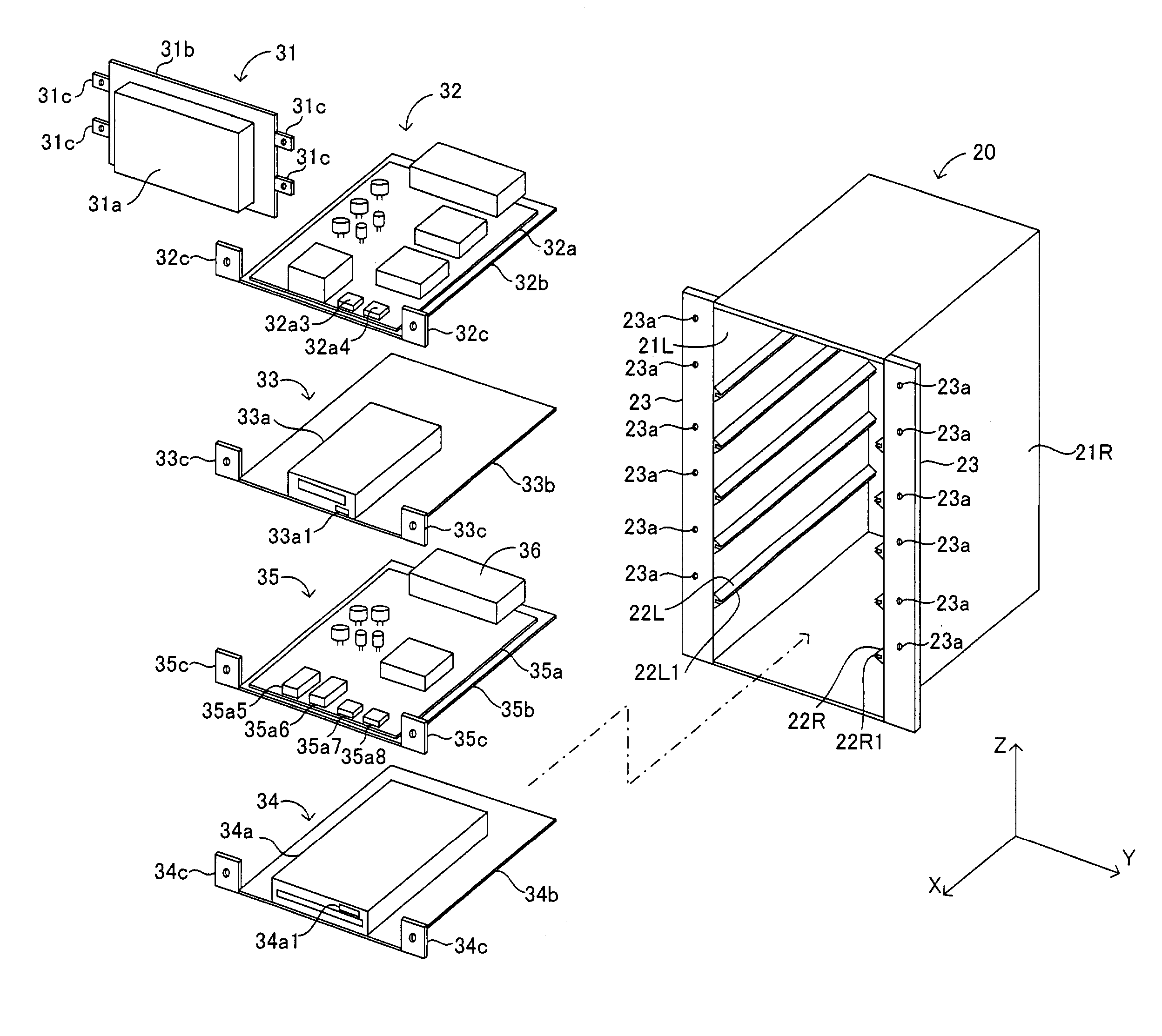
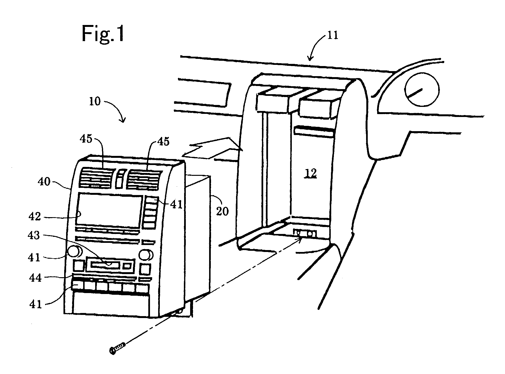
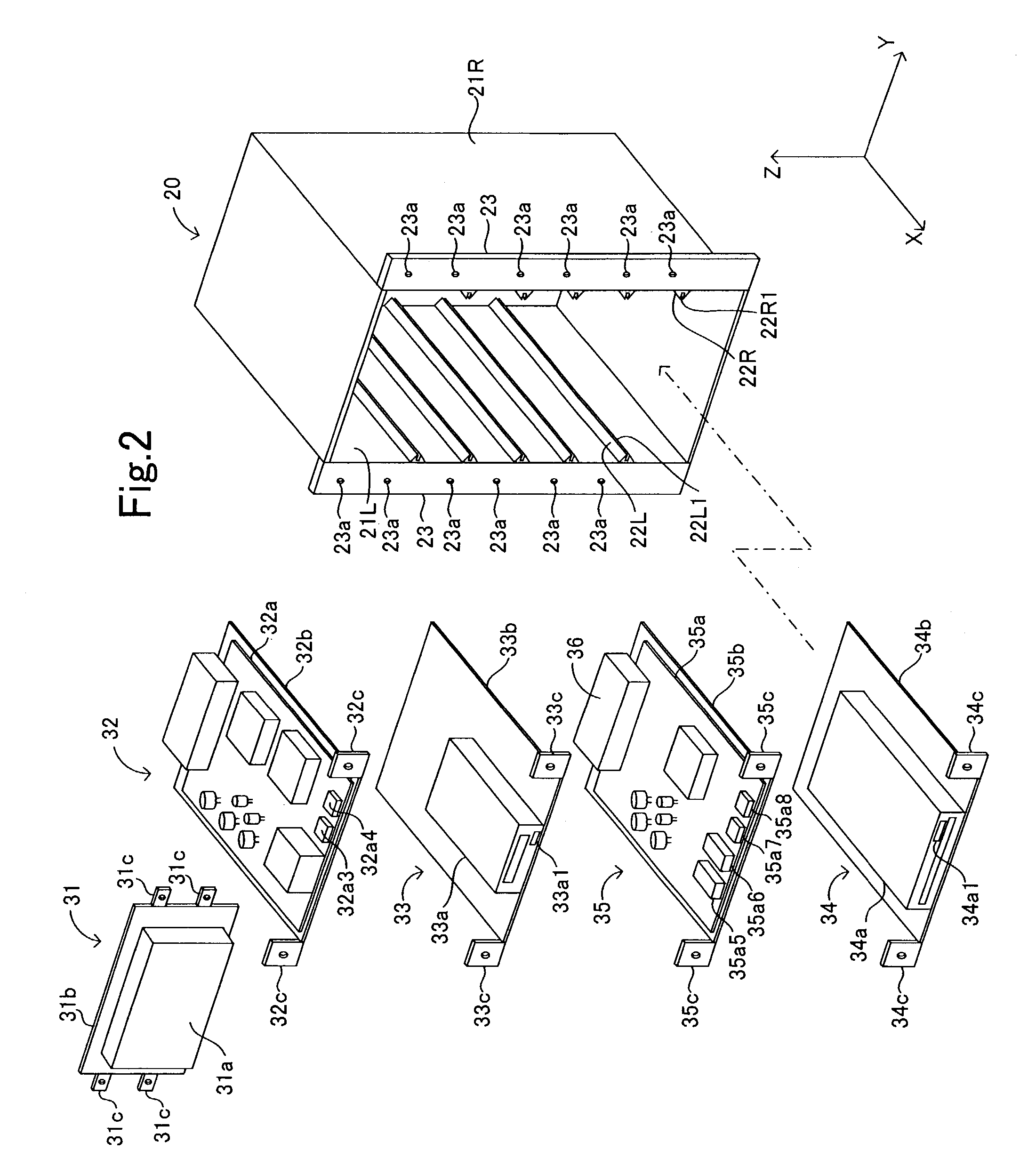
[0029]As shown in FIG. 1, an electronic equipment system 10 according to the present invention is built into a space 12, which is provided within an instrument panel 11 of a vehicle to be located between a driver seat and a front passenger seat, and is fixed to the vehicle. The electronic equipment system 10 provides a specific operation (such as navigation or music play) in accordance with operation by a driver or a front passenger. The electronic equipment system 10 is composed of a housing 20, which is completely accommodated within the space 12 and fixed to the vehicle by use of bolts; a plurality of modules 31 to 35, which are removably built in and fixed to the housing 20, as shown in FIG. 2 (exploded perspective view of the system) and FIG. 3 (schematic sectional view of the system); and an operation panel 40, which is removably fixed to the housing 20.

[0030]As shown in FIG. 2, the housing 20 is a box of a generally rectangular parallelepiped shape. A face (parallel to a Y-Z ...


PUM


Abstract

An electronic equipment system includes a housing 20 and a plurality of modules 31 to 35, which are removably built in and fixed to the housing 20. The modules 31 to 34 includes a liquid crystal display 31a; a graphic control circuit 32a1 and a navigation control circuit 32a2; an MD unit 33a; and a CD unit 34a, respectively. The module 35 is formed through integration of control sections, such as constant-voltage circuits for power supply, which achieve a function that is common among the graphic control circuit and the navigation control circuit, the MD unit, and the CD unit. Thus, it becomes possible to replace only necessary one among the modules 31 to 34, thereby reducing cost necessary for upgrading of the system.

Description

TECHNICAL FIELD[0001]The present invention relates to a vehicle electronic-equipment system which is mounted on a vehicle and includes a plurality of electronic equipment subsystems each performing a certain operation in response to an operation of an occupant.BACKGROUND ART[0002]In general, such a vehicle electronic-equipment system is configured in the form of an aggregate of subsystems including a navigation system; an audio system including a radio and a cassette deck; a compact disk (CD) system; and a mini-disc (MD) system. Each of these subsystems is composed of a single electronic equipment unit, or a unit group including two electronic equipment units, in order to provide a required specific operation.[0003]A manner of mounting the above-described vehicle electronic-equipment system onto a vehicle will be described with reference to FIG. 6. In the illustrated example, an electronic control unit 61 for a navigation system is disposed within a trunk of the vehicle; and a displ...

Claims


Application Information

Patent Timeline
IPC IPC(8): H02G3/08H02G3/00B60R11/00B60R11/02G11B33/02G11B33/12H04B1/08H04B1/20
CPCB60R11/02G11B33/126G11B33/128B60K37/04B60R11/0211B60R11/0258B60R11/0264B60R2011/0005B60R2011/0045B60R2011/0047B60R2011/0288B60R2011/0294H04B1/082H04B1/20B60K2350/941B60R11/0235B60K2370/81
Inventor NAGASAKA, YASUHIROSHIGA, TSUNEOMURATA, MASAAKI
Owner TOYOTA JIDOSHA KK
Why Eureka
Try Eureka