Ground-fault detecting device and insulation resistance measuring device

a ground-fault detection and measuring device technology, applied in the direction of electric devices, testing circuits, instruments, etc., can solve the problems of low resistance to noise on the vehicle side, low sensitivity of insulation resistance detection, low ground-fault detection accuracy, etc., to increase the sensitivity and accuracy of ground-fault detection, and high resistance to noise

Active Publication Date: 2006-01-10
YAZAKI CORP
View PDF4 Cites 69 Cited by
  • Summary
  • Abstract
  • Description
  • Claims
  • Application Information

AI Technical Summary

Benefits of technology

[0015]It is therefore an object of the present invention to provide a ground-fault detecting device which increases the sensitivity and accuracy of ground-fault detection and is highly resistant to noise as well as an insulation resistance measuring device for measuring an insulation resistance value at the occurrence of a ground fault.

Problems solved by technology

(1) The sensitivity of detection of an insulation resistance is low.
(2) The ground-fault detection accuracy is low because a ripple that appears after the smoothing is an error factor.
(3) The resistance to noise on the vehicle side is low.
(4) The accuracy lowers due to a variation in the vehicle-side capacitance.

Method used


Image

  • Ground-fault detecting device and insulation resistance measuring device
  • Ground-fault detecting device and insulation resistance measuring device
  • Ground-fault detecting device and insulation resistance measuring device

Examples


first embodiment

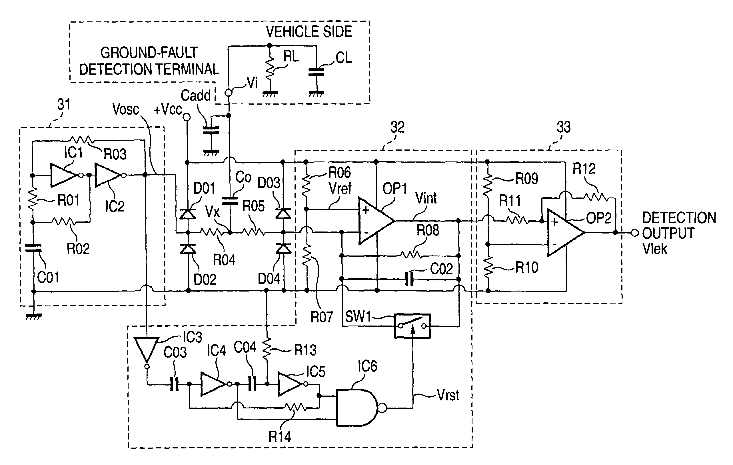
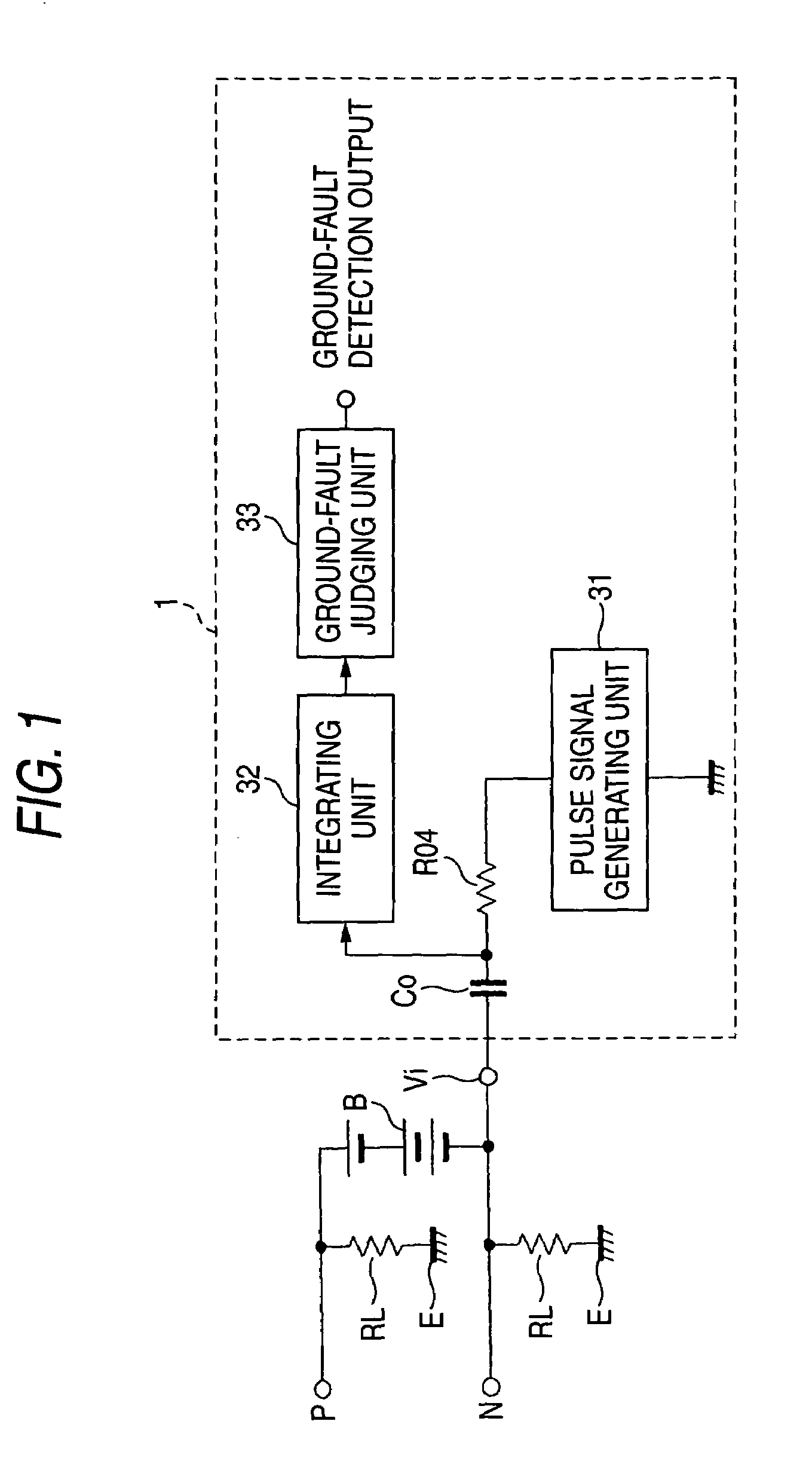
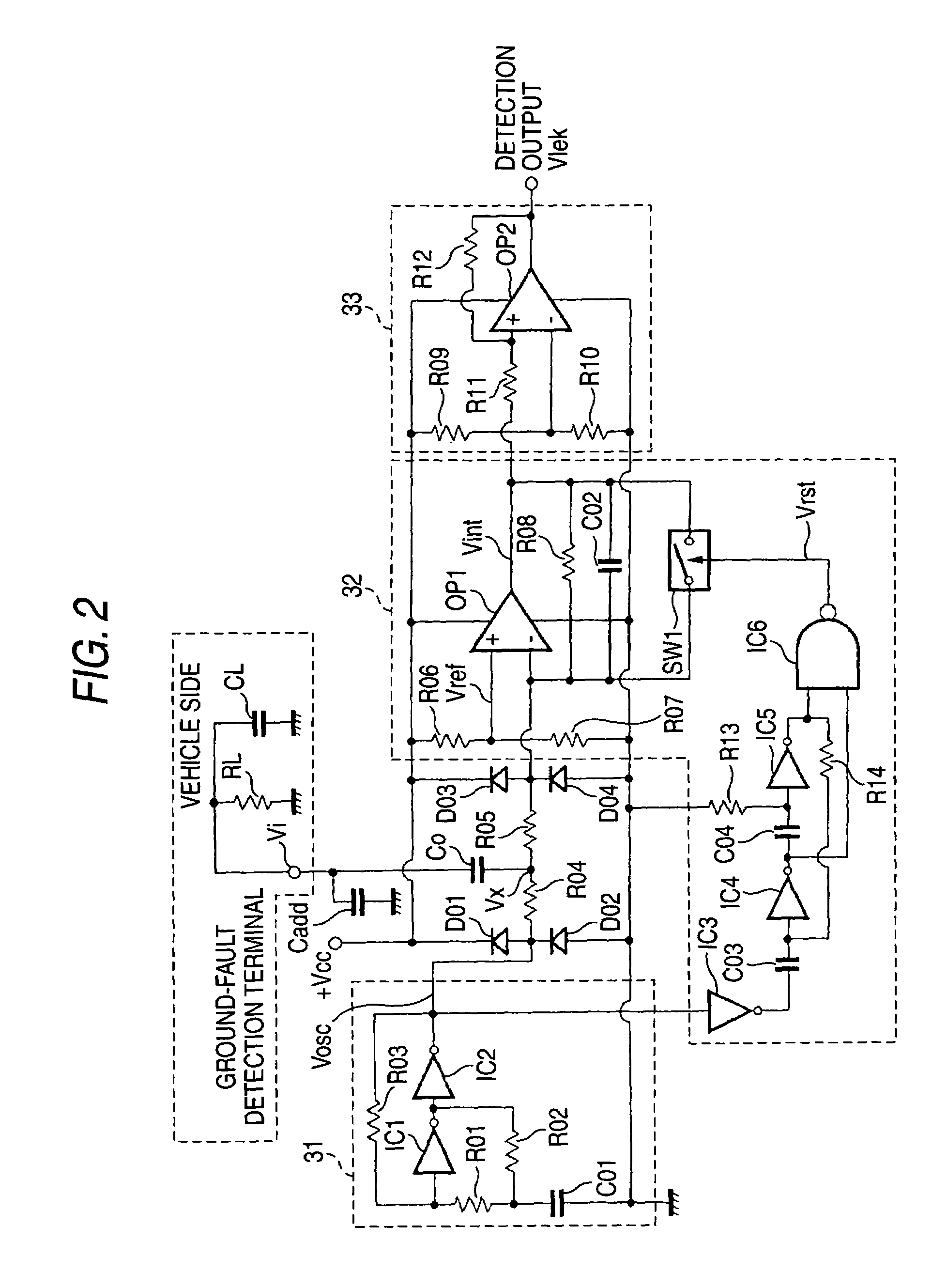
[0054]Embodiments of the present invention will be hereinafter described with reference to the drawings. FIG. 1 is a block diagram of a ground-fault detecting device according to the invention. As shown in FIG. 1, the ground-fault detecting device 1 according to the invention is to detect a ground fault to a vehicle body E in a high-voltage vehicle including a DC power source system that is batteries B that are provided as a high-voltage DC power source (e.g., 200 to 300 V) for supplying a voltage to a running drive circuit system (not shown) via a plus bus P as a DC positive-pole supply line and a minus bus N as a DC negative-pole supply line and an AC circuit consisting of an inverter etc. that is connected to the DC power source system. The ground-fault detecting device includes a pulse signal generating unit 31 for producing a pulse signal in which a high level and a low level appear repeatedly in a prescribed cycle; a series connection of a detection resistor R04 and a DC-inter...

second embodiment

[0074]Next, FIG. 4 is a circuit diagram showing a ground-fault detecting device according to the invention. The circuit of FIG. 4 is approximately the same as the circuit of FIG. 2 except for the following points. The pulse signal generating unit 31 is different in configuration from that shown in FIG. 2 in that the former is composed of a trigger signal input terminal Vtg to which a rectangular pulse signal is input from an external rectangular wave signal source (not shown), a transistor Q1, resistors R15, R16, and R17, and an inverter IC9 and produces, at the output terminal of the inverter IC9, an output that is similar to a rectangular pulse signal produced by the rectangular wave oscillation circuit of the circuit of FIG. 2. In the integrating unit 32, a low-pass filter which includes an operational amplifier OP3, a resistor R18, and capacitors C05 and C06 is added upstream of the integration circuit. The low-pass filter passes only the rectangular pulse signal that is supplie...


PUM


Abstract

A ground-fault detecting device includes a power source which is electrically insulated from a vehicle body, a pulse signal generator which generates a pulse signal having a high level and a low level which appear repeatedly in a prescribed cycle, a detection resistor which is connected to the pulse signal generator and the power source, a coupling capacitor which is connected to the detecting resistor in series, an integrator which integrates a difference between a first reference voltage and a detection voltage of the pulse signal at a connecting point of the detection resistor and the coupling capacitor over an integration interval, and a ground-fault determinant which judges whether a ground fault has occurred on the basis of an output of the integrator. The integration interval is at least part of a high-level interval and a low-level interval of the pulse signal.

Description

BACKGROUND OF THE INVENTION[0001]The present invention relates to a ground-fault detecting device for detecting a ground fault in high-voltage vehicles such as EVs (electric vehicles) and HEVs (hybrid electric vehicles) and an insulation resistance measuring device for measuring an insulation resistance value at the occurrence of a ground fault.[0002]For example, a ground-fault detecting circuit for an electric vehicle disclosed in JP-B-2933490 is known as a ground-fault detecting device of the above kind. As shown in FIGS. 7 and 8, this ground-fault detecting circuit is to detect a ground fault from batteries B to a vehicle body E in a running drive circuit system A of an electric vehicle. The running drive circuit system A includes the batteries B which are a high-voltage DC power source (e.g., 200 to 300 V), an inverter 2 as a DC-AC converter for converting, into AC voltages, a DC voltage which is supplied from the batteries B via a plus bus 4 as a DC positive-pole supply line an...

Claims


Application Information

Patent Timeline
Patent Type & Authority Patents(United States)
IPC IPC(8): G01R31/14G01R27/18G01R31/02
CPCB60L3/0023G01R31/025B60L3/0069B60W50/04G01R31/52
Inventor YAMAMOTO, KOICHI
Owner YAZAKI CORP
Why Eureka
Try Eureka