
System and method for generating a reference clock

a reference clock and system technology, applied in the field of binary non-return to zero (nrz) communications, can solve the problem that xor based phase detectors have limited frequency discrimination capability

Active Publication Date: 2006-01-10
MACOM CONNECTIVITY SOLUTIONS LLC
View PDF2 Cites 19 Cited by
  • Summary
  • Abstract
  • Description
  • Claims
  • Application Information

AI Technical Summary

Benefits of technology

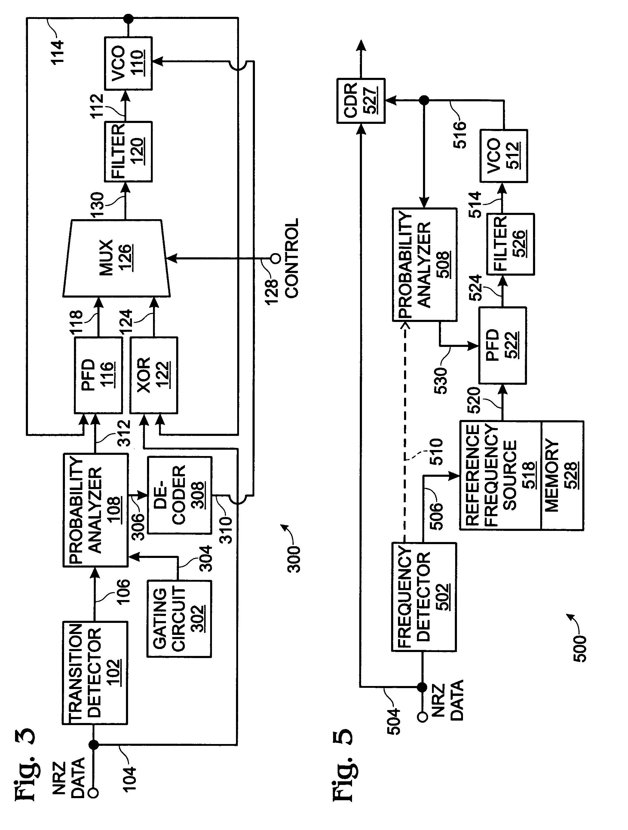
[0011]The present invention automatic data stream rate measuring system can be used as an acquisition aid for phase-locked loops in clock recovery applications. The system examines transitions in the data stream, counting those events in a given time frame, or logging the time required to accumulate a fixed count. Whether it be time or event counting, the results can be decoded into frequency band information pulling the VCO frequency into the correct range of operation, establishing a reference clock frequency for support during serial data outages, and enabling clock recovery action on the data stream.
[0012]The data stream rate measuring system can also enable a PLL to self-reference itself. Self-referencing is the ability of the measuring system to extract a deterministic signal from the data stream, and use it to pull the VCO on-frequency. Applications that don't require holdover clock stability during serial data outages can benefit from this feature by eliminating the reference clock source completely.

Problems solved by technology

XOR based phase detectors have limited frequency discrimination capability, generally restricting frequency offsets to less than the closed loop PLL bandwidth.

Method used


Image

  • System and method for generating a reference clock
  • System and method for generating a reference clock
  • System and method for generating a reference clock

Examples


Embodiment Construction

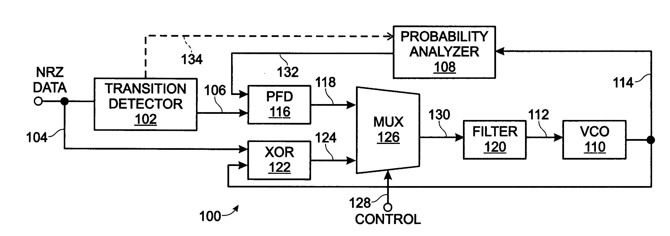
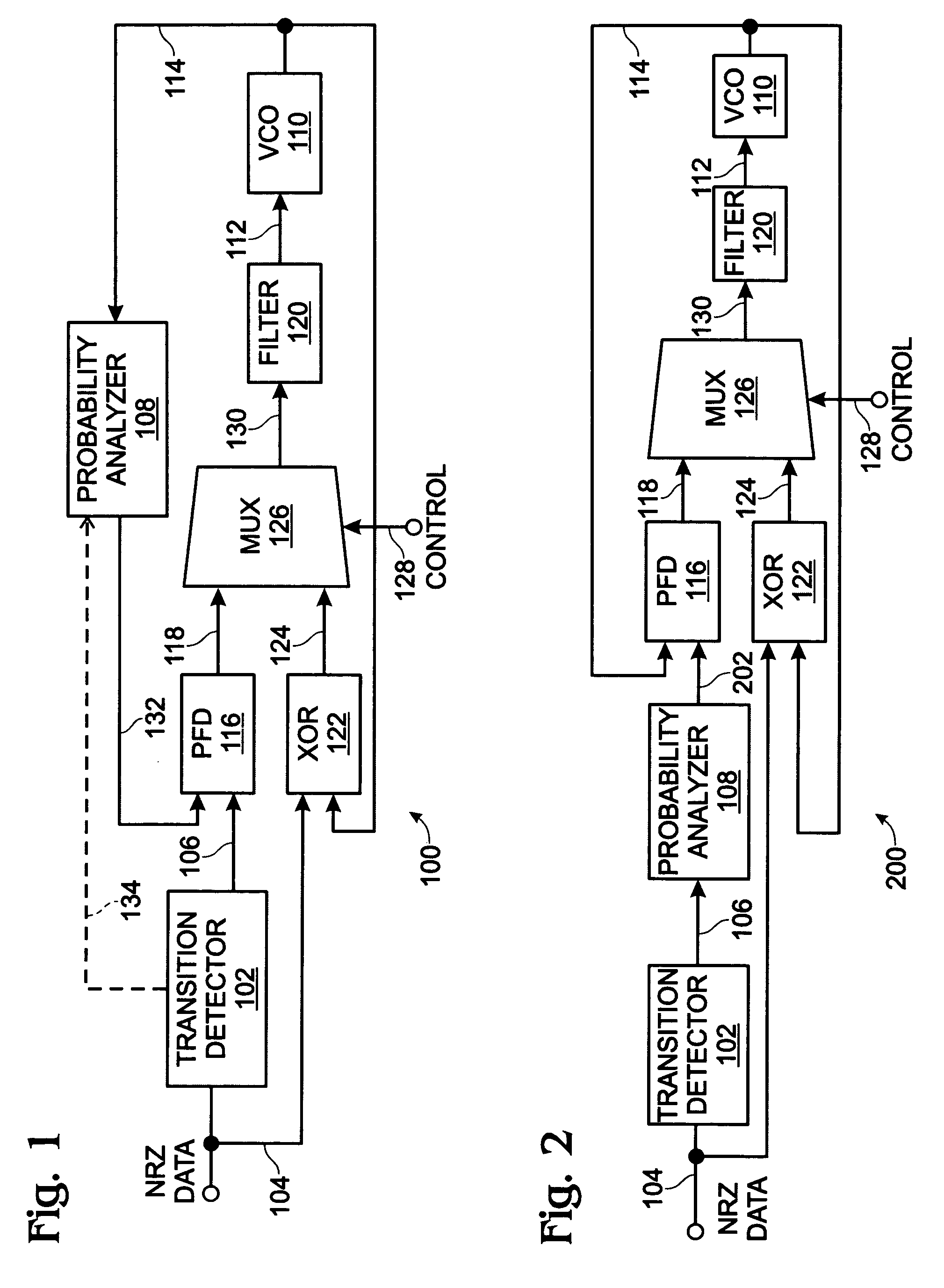
[0026]FIG. 1 is a schematic block diagram of the present invention system for synchronizing a reference clock to a pseudorandom non-return to zero (NRZ) data stream. The invention can be enabled in a communications device integrated circuit (IC) or as discrete components. The system 100 comprises a transition detector 102 having an input on line 104 to sample a pseudorandom NRZ data stream and an output on line 106 to supply a mean frequency of transitions (Fd). A probability analyzer 108 determines the transition probability (P) for the mean frequency of transitions.

[0027]A voltage controlled oscillator (VCO) 110 has an input on line 112 to accept a tuning voltage and an output on line 114 to supply a voltage controlled oscillator frequency responsive to the tuning voltage. A phase / frequency detector (PFD) 116 is responsive to the mean frequency of transitions on line 106, the transition probability, and the VCO frequency. The phase / frequency detector 116 has an output on line 118 ...


PUM


Abstract

A system and method are provided for synchronizing a reference clock to a pseudorandom non-return to zero (NRZ) data stream in a clock data recovery system. The method comprises: sampling a pseudorandom NRZ data stream; determining a mean frequency of transitions (Fd) in the data stream; determining a transition probability (P) associated with the mean frequency of transitions; using a phase / frequency detector responsive to a VCO frequency, the mean frequency of transitions, and the transition probability; in response to using the phase / frequency detector, supplying a voltage controlled oscillator tuning voltage; generating the VCO frequency responsive to the tuning voltage; using a XOR phase detector to compare the VCO frequency to the NRZ data stream; in response to using the XOR phase detector, supplying a voltage controlled oscillator tuning voltage; and, generating the VCO frequency responsive to the tuning voltage. Also provided are a system and method for synchronizing a reference clock to a pseudorandom non-return to zero data stream in a clock data recovery system, and a system and method for generating a reference clock in the absence of a pseudorandom non-return to zero (NRZ) data stream in a system including a clock data recovery (CDR) unit.

Description

RELATED APPLICATIONS[0001]This application is a continuation-in-part of a pending application entitled, SYSTEM AND METHOD FOR MEASURING DATA STREAM RATES, invented by John King, Ser. No. 10 / 044,320, filed Jan. 10, 2002.BACKGROUND OF THE INVENTION[0002]1. Field of the Invention[0003]This invention generally relates to binary non-return to zero (NRZ) communications and, more particularly, to a system and method for acquiring voltage controlled oscillator (VCO) frequency ranges, generating a reference clock, and for generating a recovered clock in the absence of a data stream.[0004]2. Description of the Related Art[0005]Voltage controlled ring oscillators are commonly used in monolithic clock data recovery (CDR) units, as they're easy to fabricate provide reliable results. Ring oscillators obtain their tuning characteristics by changing the variable delay around the ring, usually in response to a dedicated control voltage input (tuning voltage). Voltage controlled ring oscillators can,...

Claims


Application Information

Patent Timeline
Patent Type & Authority Patents(United States)
IPC IPC(8): H03D3/24H03M5/14
CPCH03M5/14
Inventor KING, JOHN ALFRED
Owner MACOM CONNECTIVITY SOLUTIONS LLC
Learn More