Satellite broadcasting receiver receiving signal radio waves two broadcasting satellites

a satellite broadcasting receiver and receiver technology, applied in the field of satellite broadcasting receivers, can solve the problems of large power consumption, large power supply of the tuner unit for supplying electric power to the amplifier, and the improvement of the satellite broadcasting receiving system. to achieve the effect of reducing power consumption

Inactive Publication Date: 2006-01-10
SHARP KK
View PDF9 Cites 23 Cited by
  • Summary
  • Abstract
  • Description
  • Claims
  • Application Information

AI Technical Summary

Benefits of technology

[0021]One object of the present invention is to provide a satellite broadcasting receiver operating with reduced power consumption.

Problems solved by technology

However, such an improved satellite broadcasting receiving system still suffers from the following problem.
As these four amplifiers are always set in the operation state, power consumption is large and a power supply of the tuner unit for supplying electric power to these amplifiers is also large in size.

Method used


Image

  • Satellite broadcasting receiver receiving signal radio waves two broadcasting satellites
  • Satellite broadcasting receiver receiving signal radio waves two broadcasting satellites
  • Satellite broadcasting receiver receiving signal radio waves two broadcasting satellites

Examples


Embodiment Construction

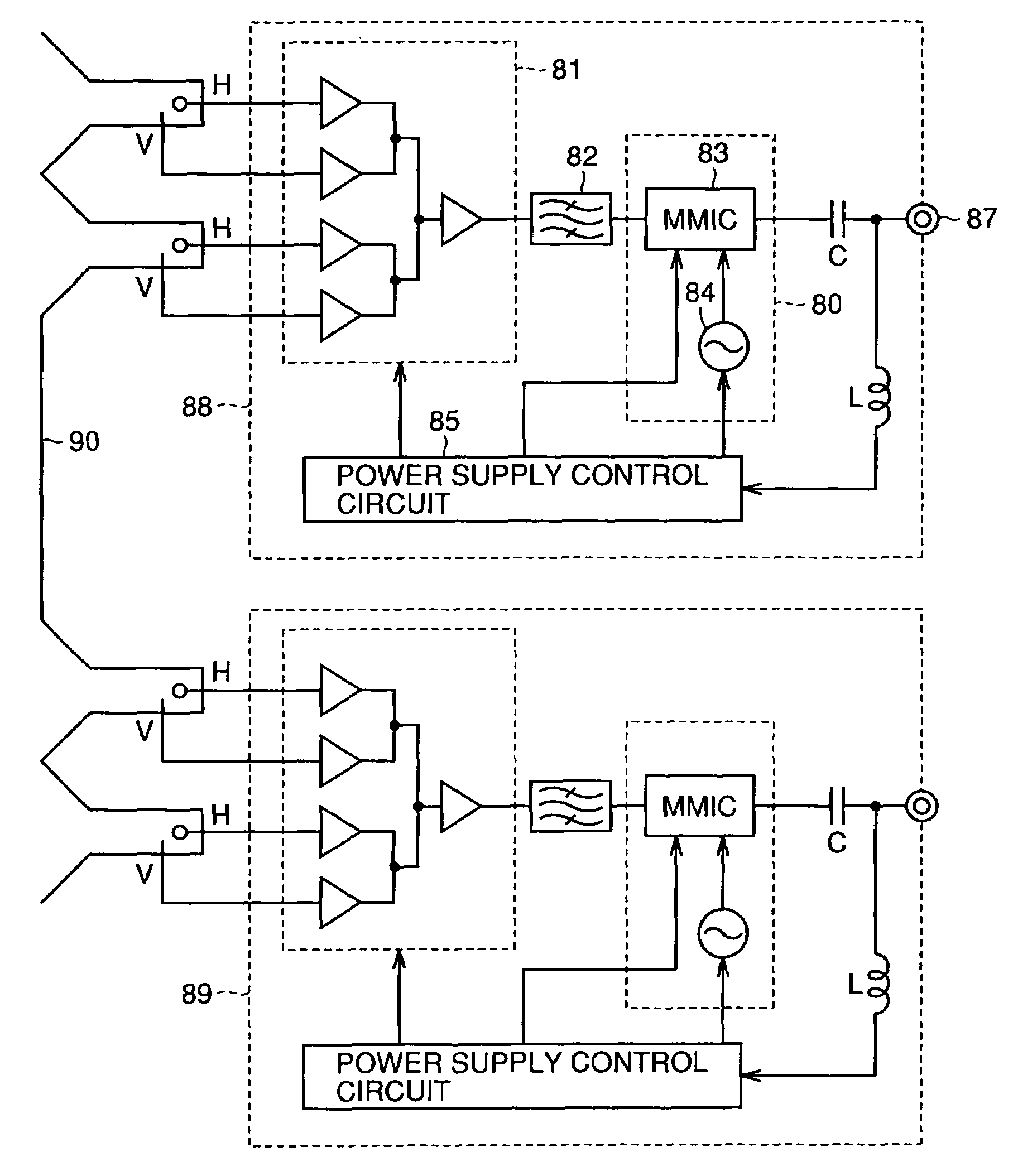
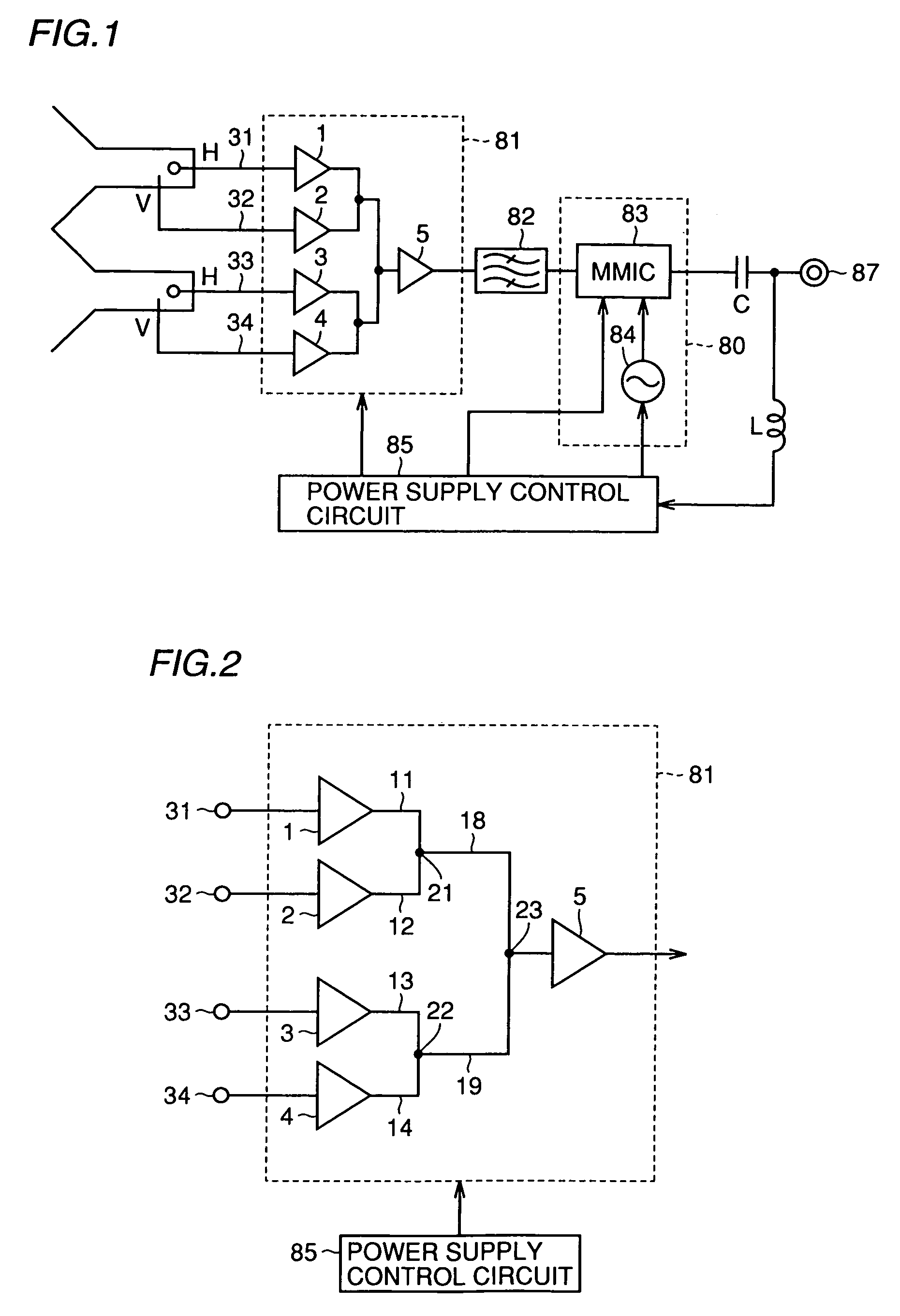
[0050]Referring to FIG. 1, a satellite broadcasting receiver, i.e., an LNB according to the embodiment of the present invention, will be described.

[0051]The LNB shown in FIG. 1 basically has a structure similar to that of a conventional LNB 100 or 200 shown in FIG. 13.

[0052]More specifically, an output from LNA 81 is applied to a frequency converting circuit 80 (including an MMIC83 and an oscillator 84) through a BPF82, and converted to an intermediate frequency signal. The resulting intermediate frequency signal is transmitted to a tuner unit (not shown) from a terminal 87 through a capacitor C. Further, a power supply control circuit 85 is supplied with electric power and a control signal through terminal 87 and an inductor L from the tuner unit (not shown).

[0053]The LNB shown in FIG. 1 is the same as LNB 100 or 200 in FIG. 13, and therefore the overlapping portion will not be described. However, as will later be described, the structure of LNA 81 shown in FIG. 1 is significantly ...


PUM


Abstract

A satellite broadcasting receiver (LNB) receiving signal radio waves from broadcasting satellites is provided with a low noise amplifier (LNA) amplifying a received signal, and a frequency converting circuit converting an output from the LNA to an intermediate frequency signal for output. The LNA includes four amplifiers in the first stage respectively amplifying four types of different received signals. A power supply control circuit sets a current flowing through one of four amplifiers at a prescribed value and sets currents flowing through all the other amplifiers at 0. Thus, the output from only one amplifier is supplied to the amplifier in the second stage for amplification and further applied to the frequency converting circuit. Accordingly, the amplifiers in the first stage do not simultaneously consume currents, and a switching circuit is not necessary.

Description

BACKGROUND OF THE INVENTION[0001]1. Field of the Invention[0002]The present invention relates to satellite broadcasting receivers and, more specifically to a satellite broadcasting receiver capable of switching and receiving signal radio waves from two broadcasting satellites.[0003]2. Description of the Background Art[0004]A conventional receiving equipment for satellite broadcasting basically includes: a reflection plate (reflection mirror) called a dish for receiving a signal radio wave transmitted from a broadcasting satellite in a geostationary orbit; a satellite broadcasting receiver receiving the signal radio wave reflected by the dish through a waveguide and performing low noise amplification on the received signal radio wave of 12 GHz band and then converting it to an intermediate frequency signal of 1 GHz to 2 GHz for output; and a tuner unit selecting and demodulating a desired signal band from the intermediate frequency signal supplied from the satellite broadcasting rece...

Claims


Application Information

Patent Timeline
Patent Type & Authority Patents(United States)
IPC IPC(8): H04H1/00H01Q23/00H01Q1/24H01Q13/02H01Q25/00H03F3/189H03F3/68H03F3/72H04B1/18H04B1/26
CPCH01Q1/247H01Q13/0258H01Q25/001H03F3/189H04B1/18H03F3/72H03F3/68H03F2200/294H03F2200/372
Inventor KATO, MASAHIRO
Owner SHARP KK
Why Eureka
Try Eureka