Radio frequency control for communication systems

a technology of communication system and radio frequency control, applied in the direction of transmission monitoring, electrial characteristics varying frequency control, duplex signal operation, etc., can solve the problem of vcxo frequency, achieve low cost, improve signal-to-quantization noise ratio, and achieve easy implementation

Inactive Publication Date: 2006-01-10
AVAGO TECH WIRELESS IP SINGAPORE PTE
View PDF10 Cites 87 Cited by
  • Summary
  • Abstract
  • Description
  • Claims
  • Application Information

AI Technical Summary

Benefits of technology

[0038]FIG. 2 is a block diagram showing the preferred embodiment of the downlink digital phase rotator 20. Each complex (inphase and quadrature components) baseband digital sample 19 is rotated in the complex plane by complex multiplication with complex rotator vector 87 to obtain rotated complex output phasor 21. The complex rotator vector 87 has a real and an imaginary part that are equal respectively to the cosine and sine of the rotation angle θn for the n-th complex phasor. The sine and cosine values are read from a sine lookup table 86 having 256 entries of 16-bit sine values for rotation angles in the first quadrant. The input 85 to lookup table 86 is a 10-bit word representing the current rotation angle θn in radians modulo 2π. The two most significant bits of the input word determine the quadrant of the rotation angle, and the eight least significant bits determine the table lookup address. For a commanded downlink frequency offset Δf the rotation angle increases at a constant rate per sample interval and this monotonically changing phase angle θn is represented by a modulo-216 accumulator with adder 80 and delay element 82. The input to the phase accumulator 80 is a 16-bit word representing the normalized downlink frequency offset command 216Δf / Rs, where Δf is the downlink offset command in Hz, and Rs is the GMSK symbol rate of 270.833 KHz. The frequency resolution of the downlink phase rotator 20 is 4.1 Hz for the 16-bit accumulator word size in the preferred embodiment. Finer resolution can be achieved if desired by simply increasing the word size of the accumulator 80 (for example, frequency resolution of 0.016 Hz for 24-bit word size). This is in contrast with the much larger 30 Hz resolution described earlier for the VCXO DAC method of frequency control for the case of 10 bit DAC and a high quality VCXO. An advantage of the phase rotator method of frequency control of the invention is that the frequency resolution is fixed and not dependent on the quality of the VCXO. In contrast with the conventional VCXO DAC method of frequency control a lower quality VCXO or VCXO crystal will generally exhibit larger frequency quantization error. Thus a further advantage of the invention is that generally the use of lower cost VCXO is possible using the downlink phase rotator for receiver frequency control for a given frequency error tolerance.
[0039]In FIG. 2 the 16-bit inphase and quadrature quantization error at the downlink phase rotator output is not a significant source of phase distortion or frequency error. In FIG. 2, the signal-to-quantization noise ratio is 96 dB for a full scale signal, and allowing for 10 dB AGC headroom and 28 dB signal multipath fade the signal-to-quantization noise ratio is still better than 58 dB during a signal fade. In FIG. 1, the AGC function 26 measures average signal amplitude in the baseband complex signal 21 and sets the gain of PGA 16 by means of AGC command 27 so that the average signal amplitude over many fades remains at approximately 10 dB below saturation, thereby maintaining the ADC resolution and associated signal to quantization noise ratio at an acceptable level. The preferred embodiment of the downlink phase rotator illustrated in FIG. 2 with the preceding phase and frequency error characteristics is easily implemented in a low cost 16-bit fixed point DSP.
[0040]For most modulation types, a digital data modulator may be configured to generate a baseband complex output (inphase and quadrature outputs). In that case for fine uplink frequency control the downlink phase rotator design of FIG. 2 may also be used analogously for the uplink phase rotator to operate on the complex modulator output. Because there is no signal fading associated with the modulator output, the signal-to-quantization ratio is typically higher at the uplink rotator output for a given output word size. However, for the GSM standard of the preferred embodiment GMSK modulation is of the class of continuous phase modulation for which a simpler uplink phase rotator embodiment of FIG. 3 is specified wherein the phase rotator is an integral part of the continuous phase data modulator. The configuration in FIG. 3 has the advantage that the modulator phase variable appears explicitly in the embodiment of continuous phase data modulator. Then phase rotation, or generation of a frequency offset simply involves addition of a constant to the modulation phase variable and complex multiplication operations normally required in the phase rotator are unnecessary. This results in a significant reduction in complexity for implementation of the uplink phase rotator.
[0041]In FIG. 3 the binary data for the next burst transmission is held in a buffer 402 and at the assigned time slot is output at the symbol rate Rs. The burst data is passed through a differential encoder 404 wherein the differential coded binary data output 405 with binary values 0 and 1 are is mapped into respective real values + / −1. Next, the differentially coded data 405 is upsampled by upsampler 406 by repetition N1=2 samples per bit, and then filtered by a pulse shaping FIR filter 408 having filter length N3=8 bits. The output 409 of the pulse shaping filter represents filtered instantaneous modulation frequency which is added to the normalized frequency offset command 64 for uplink phase rotation. Both modulation frequency 409 and frequency offset command 64 are combined and converted to modulator phase by the integrator comprising a summer 410 and a delay element 412. The summer 410 is a modulus summer to reflect the cyclic nature of phase modulo-2π and the modulus is selected to achieve desired frequency resolution for both modulation and uplink frequency shift corresponding to the commanded frequency offset 64 for the uplink phase rotator. For the preferred embodiment the phase modulus is 220 corresponding to the selection of a 20 bit word for representation of normalized frequency offset 64, and frequency modulation 409. The 20-bit modulator phase is truncated to 10 bits as the sine lookup table input variable 415. The resultant cosine and sine values 417, 419 returned by the lookup table 416 represent modulator inphase and quadrature outputs respectively at the sample rate of N1 samples per modulation symbol. The lookup table contains 256 values of the sine function in the first quadrant and the table suffices for generation of both sine and cosine over all four quadrants, where the quadrant of the phase angle 415 is indicated by the two most significant bits. The modulator inphase and quadrature components are upsampled by a factor N2 by respective interpolation filters to minimize quantization error in the uplink DAC conversion 44 that follows. The resultant complex baseband modulator output components 43, which have a sample rate of Rs*N1*N2, or N1*N2 samples per symbol, are then processed by the pair of uplink DACs 44. The values for parameters N1, N2, and N3 indicated in the table in FIG. 3 for the preferred embodiment are suitable for the specifications of the GSM standard. For other systems which may employ other continuous phase modulation types other parameter values may be used as known to those of ordinary skill in the art.
[0042]The uplink frequency control resolution for the uplink phase rotator in FIG. 3 is 0.51 Hz. Any degree of finer resolution can be achieved by simply increasing the word size of the frequency variables 64, 409, and 413. This is in contrast with the much poorer 30 Hz resolution described earlier for VCXO DAC frequency control for the high quality VCXO with 10-bit DAC. Further, as in the case of the downlink phase rotator an advantage of the method of frequency control by uplink phase rotator in the invention is that the frequency resolution is fixed and not dependent on the quality of the VCXO. In contrast with the conventional VCXO DAC method of frequency control a lower quality VCXO or VCXO crystal will generally exhibit larger frequency quantization error. Thus a further advantage of the invention is that the use of lower cost VCXO is facilitated by the method of frequency control by phase rotators in the invention.
[0043]In FIG. 1 the LO / synthesizer produces the local oscillator signals 35 and 37 for the downconverter and upconverter respectively by means such as in Ref. [3] known to those of ordinary skill in the art. The LO synthesizer is comprised typically of voltage controlled oscillators and synthesizers wherein the VCO's generate nominal uplink and downlink local oscillator frequencies, and the synthesizers generate small frequency offsets for tuning of local oscillators to the assigned channel frequencies. When the VCXO is operating at its specified reference frequency exactly, for

Problems solved by technology

This is because temperature changes induce VCXO frequency errors that approximate a ramp over intervals of time of the order of tracking loop time constants.

Method used


Image

  • Radio frequency control for communication systems
  • Radio frequency control for communication systems
  • Radio frequency control for communication systems

Examples


Embodiment Construction

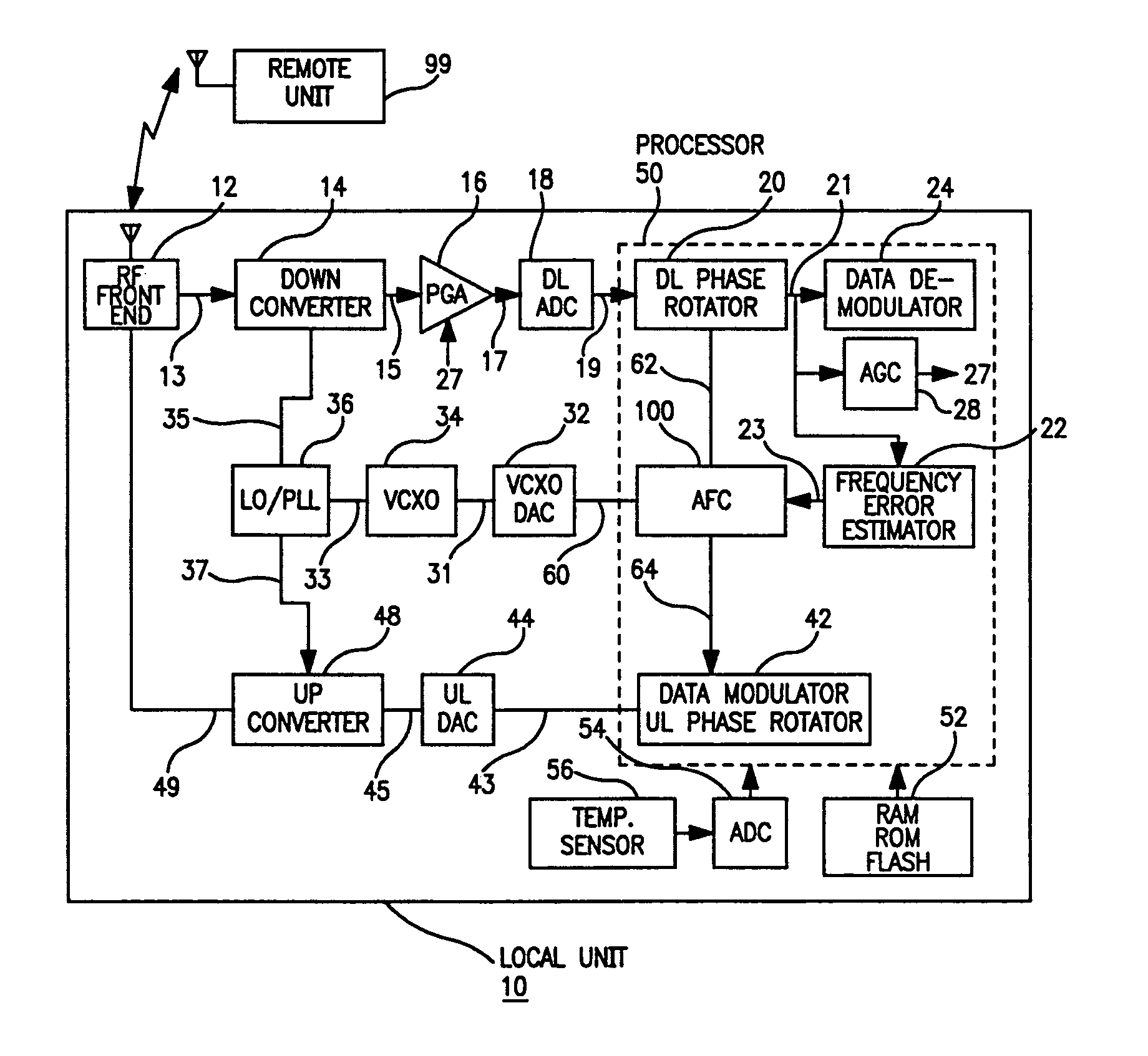
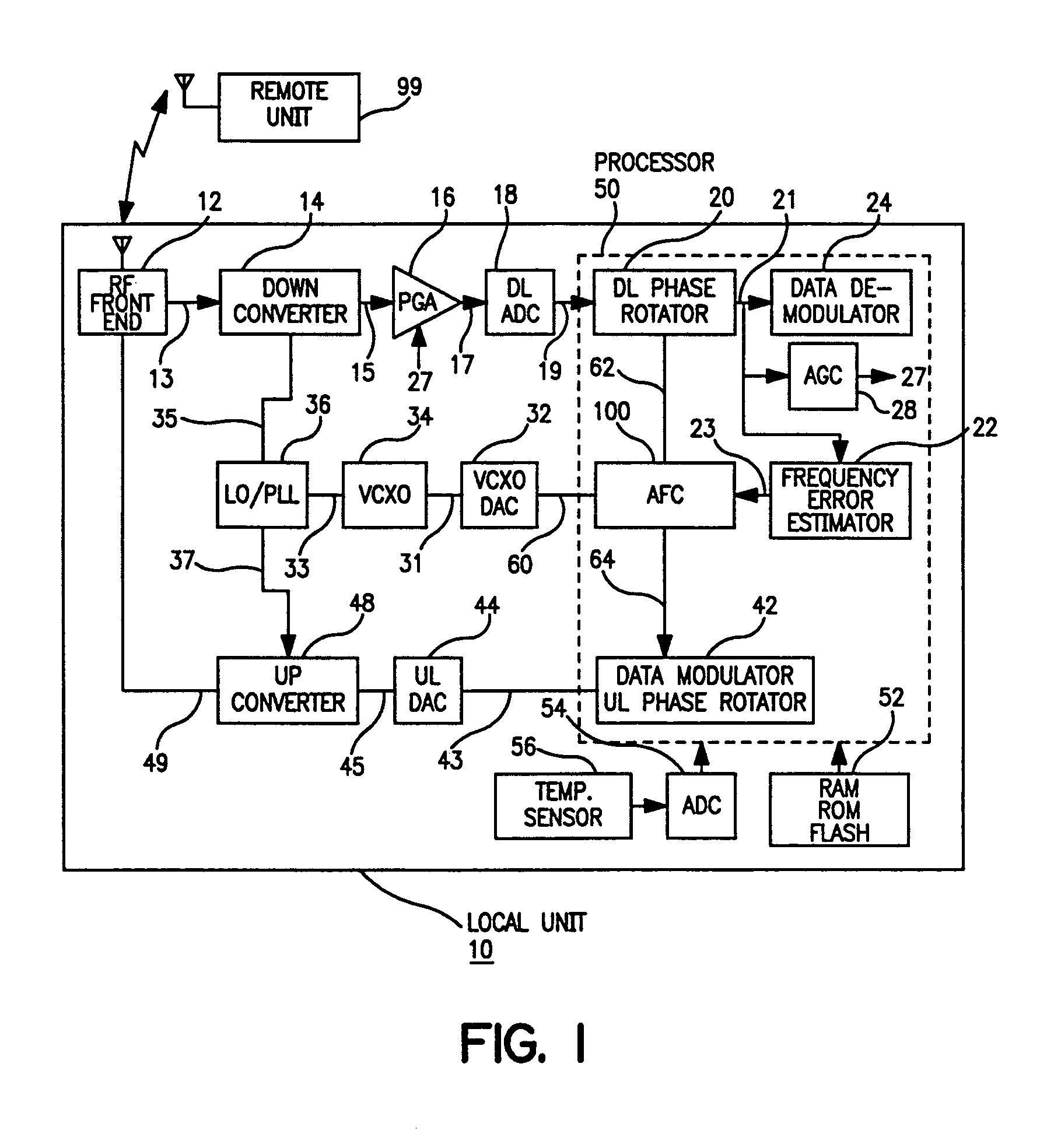
[0032]FIG. 1 shows a block diagram illustrating the preferred embodiment of the present invention. A local communication unit 10 such as a radiotelephone communicates with a remote communication unit 99 such as a cellular phone base station. In the preferred embodiment the local unit and the remote unit adhere to the Global System for Mobile communications (GSM) standard as an illustrative example. However, the invention is not restricted to the GSM standard and applies more generally to any system in which local unit derives its transmitter and receiver frequency by frequency tracking of radio transmissions from the remote station. Therefore, in FIG. 1 on the downlink transmission from remote to local unit, the radio frequency is one of a plurality of GSM channels allocated in the 935 to 960 MHz frequency band with a channel spacing of 200 KHz. On the uplink transmission from local to remote unit, the radio frequency is one of a plurality of GSM physical channels allocated in the 8...


PUM


Abstract

The present invention provides for a system and method for improvement of radio transmitter and receiver frequency accuracy for a local radio communication unit that communicates digital data with a remote communication unit. In the local unit the received radio signal is down-converted, and converted to complex baseband digital samples by an analog-to-digital converter. A downlink digital phase rotator applies a fine frequency shift to the samples in accordance with a receiver frequency offset command. The resultant baseband signal is used by the data demodulator and by a receiver frequency error estimator to obtain receiver frequency errors. A data modulator generates baseband complex samples which are shifted in carrier frequency by an integrated uplink digital phase rotator in accordance with a transmitter frequency offset command. The modulated samples are then converted by a digital-to-analog converter and upconverted in frequency for radio transmission to the remote unit. The local oscillator signals for both upconverter and downconverter are phase locked to a reference frequency generated by a VCXO. An automatic frequency control (AFC) function nulls the transmitter and receiver frequency error by the frequency adjustment commands to the uplink and downlink phase rotators or to the VCXO digital-to-analog converter (VCXO DAC) by feedback control principals based on measured receiver frequency error. During frequency track mode when communications between local and remote units are possible, the AFC only adjusts radio frequency via phase rotator commands and the VCXO command remains fixed, thereby avoiding communications performance degradation by VCXO frequency quantization error due to the VCXO DAC. The AFC adjusts VCXO frequency only during a preliminary acquisition mode prior to data communications, or to back out excessively large frequency offsets accumulated in the downlink and uplink phase rotators during track mode. When a VCXO adjustment is made in track mode, phase rotator adjustments are simultaneously applied to cancel the errors in transmitter and receiver radio frequencies caused by the step change due to VCXO frequency quantization thereby mitigating VCXO frequency quantization noise.

Description

CROSS REFERENCES TO RELATED APPLICATIONS[0001]This application is a continuation of U.S. patent application Ser. No. 10 / 266,083, filed Oct. 7, 2002, and now issued as U.S. Pat. No. 6,816,716, which is a continuation of Ser. No. 09 / 477,720, filed Jan. 5, 2000, now issued as U.S. Pat. No. 6,463,266, which claims priority pursuant to 35 U.S.C. 119(e) to U.S. Provisional Application Ser. No. 60 / 147,821 filed Aug. 10, 1999, all of which are incorporated herein by reference in their entirety.BACKGROUND OF THE INVENTION[0002]1. Field of the Invention[0003]This invention relates to apparatuses and methods for improvement of radio transmitter and receiver frequencies of a local radio communication unit that is communicating digital data with a remote communication unit.[0004]2. Description of Related Art[0005]Communication systems often comprise a plurality of local units such as radiotelephone handsets that communicate digital data by radio transmissions with a remote unit such as a cellula...

Claims


Application Information

Patent Timeline
Patent Type & Authority Patents(United States)
IPC IPC(8): H04B1/18H04B1/38H03J7/04H04B1/26H04L27/00
CPCH03J7/04H04B1/26H04L2027/0028H04L2027/0022
Inventor SHOHARA, AKI
Owner AVAGO TECH WIRELESS IP SINGAPORE PTE
Why Eureka
Try Eureka