
Quantum bit with a multi-terminal junction and loop with a phase shift

a phase shift, multi-terminal junction technology, applied in the field of quantum computing, can solve the problems of long-range electric interaction, difficult expansion of such systems to a commercially useful number of qubits, and the basis state used is not naturally degenera

Inactive Publication Date: 2006-01-17
D WAVE SYSTEMS INC
View PDF6 Cites 39 Cited by
  • Summary
  • Abstract
  • Description
  • Claims
  • Application Information

AI Technical Summary

Benefits of technology

The present invention relates to a qubit that uses a multi-terminal junction with a superconducting loop to create a phase shift. The phase shift can be controlled by a magnetic field or an external current source. The qubit can be constructed with any superconducting material and can have any desired number of terminals. The asymmetric junction in the qubit allows for biasing of one of the ground states and can be used to perform a σz quantum gate operation. The qubit can also be selectively entangled with other qubits in a qubit array. The technical effects of the invention include improved precision and control in quantum computing and improved performance of qubits in quantum information processing.

Problems solved by technology

However, efforts to expand such systems to a commercially useful number of qubits face difficult challenges.
A problem with this system is that the charge of the island in the state having the extra Cooper pair causes long range electric interactions that interfere with the coherence of the state of the qubit.
A problem with this system is that the basis states used are not naturally degenerate and the required biasing field has to be extremely precise.
This biasing is possible for one qubit, but with several qubits, this bias field fine-tuning becomes extremely difficult.
Another problem is that the basis states used are typically not the ground states of the system, but higher energy states populated by external pumping.
Inevitably, these qubits are only useful when controlled by magnetic fields, or by some other means which couple the qubit to the environment or provide other potential sources of decoherence.
In order to overcome these sources of decoherence, a large amount of overhead is required to control and harvest the quantum power available from the qubit.
However, the means by which this can be accomplished has as yet eluded scientists.

Method used


Image

  • Quantum bit with a multi-terminal junction and loop with a phase shift
  • Quantum bit with a multi-terminal junction and loop with a phase shift
  • Quantum bit with a multi-terminal junction and loop with a phase shift

Examples


Embodiment Construction

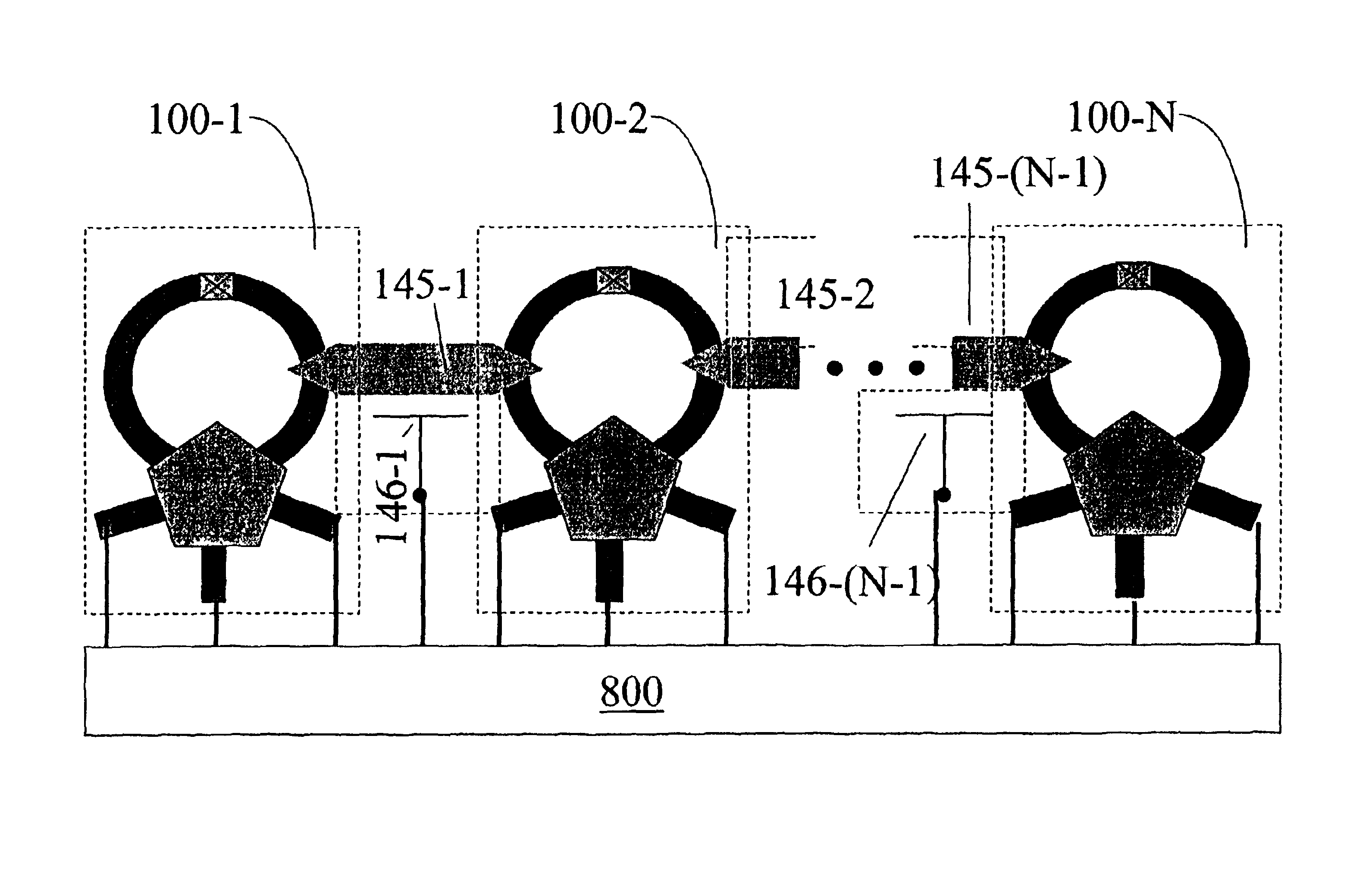
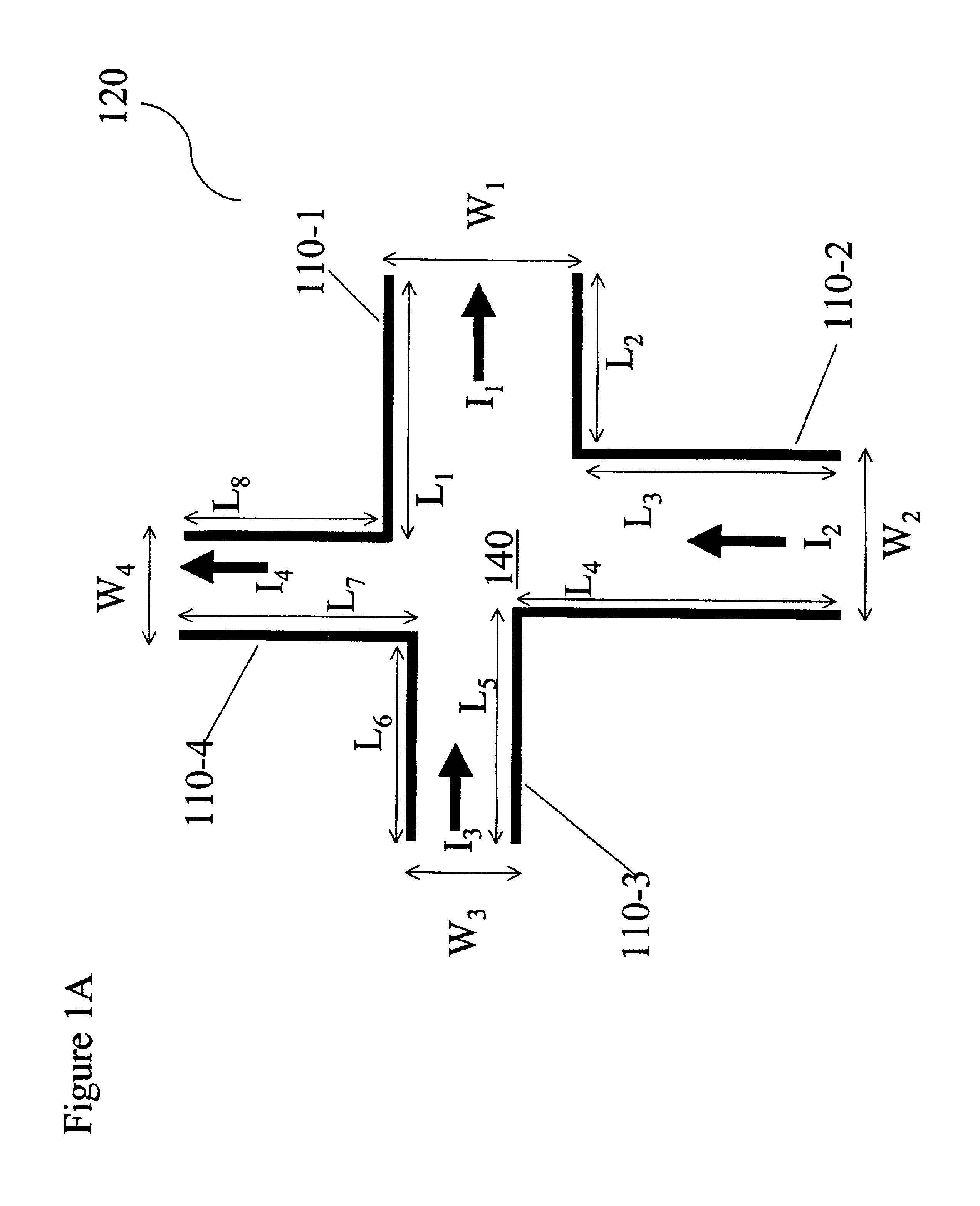
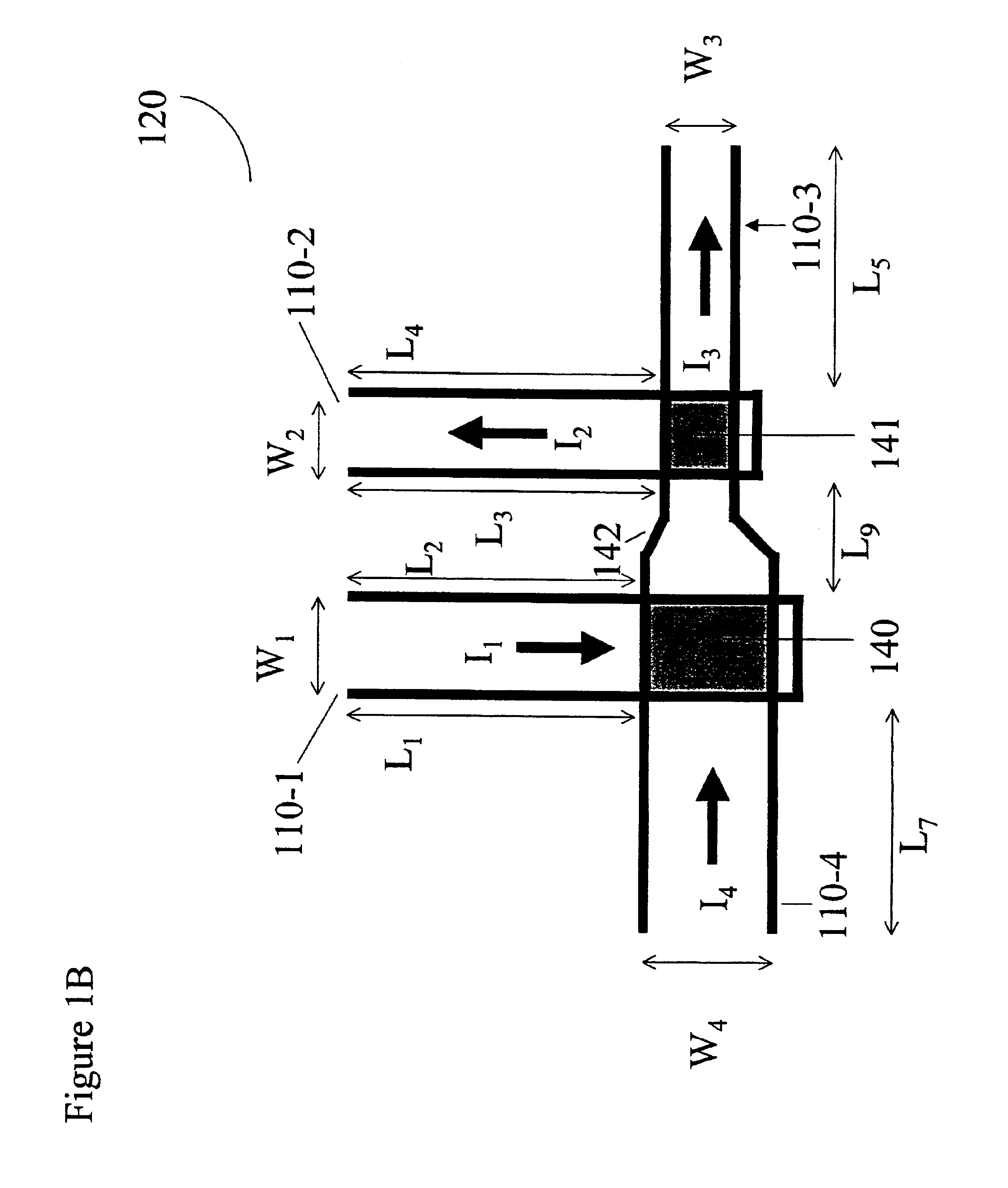
[0050]In accordance with embodiments of the invention, a quantum computing operation can be performed on an array of quantum qubits where at least one of the qubits includes a qubit according to the present invention. A qubit according to the present invention includes a multi-terminal junction where two terminals of the multi-terminal junction are joined to form a superconducting loop. The superconducting loop introduces a phase shift to the superconducting order parameter. In some embodiments, the superconducting loop includes an intrinsic phase shifter.

[0051]Intrinsic phase shifters in superconducting phase quantum bits (qubits) are disclosed in M. H. S. Amin, T. Duty, A. Omelyanchouk, G. Rose and A. Zagoskin, U.S. Provisional Application Ser. No. 60 / 257624, “Intrinsic Phase Shifter as an Element of a Superconducting Phase Quantum Bit”, filed Dec. 22, 2000, herein incorporated by reference in its entirety. A phase shifting structure with 0 and π-phase shifts in a two-terminal DC ...


PUM


Abstract

A solid-state quantum computing qubit includes a multi-terminal junction coupled to a superconducting loop where the superconducting loop introduces a phase shift to the superconducting order parameter. The ground state of the supercurrent in the superconducting loop and multi-terminal junction is doubly degenerate, with two supercurrent ground states having distinct magnetic moments. These quantum states of the supercurrents in the superconducting loop create qubits for quantum computing. The quantum states can be initialized by applying transport currents to the external leads. Arbitrary single qubit operations may be performed by varying the transport current and / or an externally applied magnetic field. Read-out may be performed using direct measurement of the magnetic moment of the qubit state, or alternatively, radio-frequency single electron transistor electrometers can be used as read-out devices when determining a result of the quantum computing. Further, qubits as described above can form arrays of qubits for performing controlled quantum computing calculations. In one example, an array of qubits can be utilized as a random number generator.

Description

RELATED APPLICATIONS[0001]This application is related to concurrently filed application Ser. No. 09 / 839,637 entitled “Quantum Bit with a Multi-Terminal Junction and Loop with a Phase Shift” and application Ser. No. 09 / 839,991 entitled “Quantum Bit with a Multi-Terminal Junction and Loop with a Phase Shift”, both of which are herein incorporated by reference in their entirety.BACKGROUND[0002]1. Field of the Invention[0003]This invention relates to quantum computing and, more specifically, to solid state quantum computing qubits with superconducting materials.[0004]2. Discussion of Related Art[0005]Research on what is now called quantum computing traces back to Richard Feynman, See, e.g., R. Feynman, Int. J. Theor. Phys., 21, 467-488 (1982). Feynman noted that quantum systems are inherently difficult to simulate with conventional computers but that observing the evolution of a quantum system could provide a much faster way to solve some computational problems. In particular, solving a...

Claims


Application Information

Patent Timeline
Patent Type & Authority Patents(United States)
IPC IPC(8): H01L39/22G06N99/00
CPCB82Y10/00G06N99/002H01L39/225H01L39/228H01L39/223Y10S977/933G06N10/00H10N60/128H10N60/124H10N60/12
Inventor AMIN, MOHAMMAD H. S.DUTY, TIMOTHYOMELYANCHOUK, ALEXANDERROSE, GEORDIEZAGOSKIN, ALEXANDREBLAIS, ALEXANDRE
Owner D WAVE SYSTEMS INC
Learn More