Polar and linear amplifier system

a linear amplifier and amplifier technology, applied in the field of electromechanical devices, can solve the problems of inefficient linear amplifier operation in these types of signals, general non-operation at high efficiency, and additional challenges, so as to facilitate linearization of the amplifier system, improve amplifier performance, and mitigate out-of-band emissions

Inactive Publication Date: 2006-01-17
NORTHROP GRUMMAN SYST CORP
View PDF12 Cites 50 Cited by
  • Summary
  • Abstract
  • Description
  • Claims
  • Application Information

AI Technical Summary

Benefits of technology

[0012]In yet another aspect of the present invention, the input signal can be modified via predistortion (e.g., especially well suited to digital pre-distortion) techniques to facilitate linearization of the amplifier system and to mitigate out-of-band emissions. Separate predistortion is applied to the polar components and the composite signal. Alternatively, the output signal can be modified by a digital cross-cancellation technique that employs a separate digital reference signal to produce a “clean” version of the wanted signal used to correct distortion in the output signal. The digital cross-cancellation technique allows for modification of the input signal to improve amplifier performance (e.g., reduction of signal peak levels) that can be corrected at the output of the power amplifier. The predistortion technique and digital cross-cancellation technique can be combined to facilitate linearization and to mitigate out-of-band emissions of the amplifier system.

Problems solved by technology

However, they are generally not operated at high efficiency due to the need to provide high linearity.
Time varying envelopes present an additional challenge.
Thus, there is customarily an inherent tradeoff between linearity and efficiency in amplifier designs.
Therefore, the operation of the linear amplifiers in these types of signals is very inefficient, since the amplifiers must have their supply voltage sized to handle the large peak voltages even though the signals are much smaller a substantial portion of the time.
Additionally, the size and cost of the power amplifier is generally proportional to the required peak output power of the amplifier.
The cost of the amplifier scales with its, peak power.
Several other circuit costs including heat sinks and DC-DC power supplies scale inversely to peak power and dissipated heat (which results from the electrical inefficiency).
Related base station costs of AC-DC power supplies, back-up batteries, cooling, and circuit breakers also scale inversely with efficiency as does the electrical operating costs.
Clearly, improving DC-RF efficiency is a major cost saver both for manufacturing and operation.
However, non-linear amplifiers can only be employed with constant envelope signals, such as frequency modulations (FM) and certain forms of phase modulation (PM), signals with modulated amplitudes cause severely distorted outputs from these classes of amplifiers.
Polar amplifiers have demonstrated very high efficiency but can distort signals and cause significant amounts of OOB emissions.
If the signal crosses through a zero-amplitude point it may cause the polar amplifier to cut-off and / or require an extremely rapid and difficult phase change in the constant envelope, PM, path.
If the signal varies over a large dynamic range it may cause the polar amplifier to operate with very low supply (e.g., drain) voltages resulting in additional signal distortion and can cause the amplifier to shutoff when the supply voltage becomes too low.
As a result, the polar amplifier has only been employed with a limited range of waveforms.

Method used


Image

  • Polar and linear amplifier system
  • Polar and linear amplifier system
  • Polar and linear amplifier system

Examples


Embodiment Construction

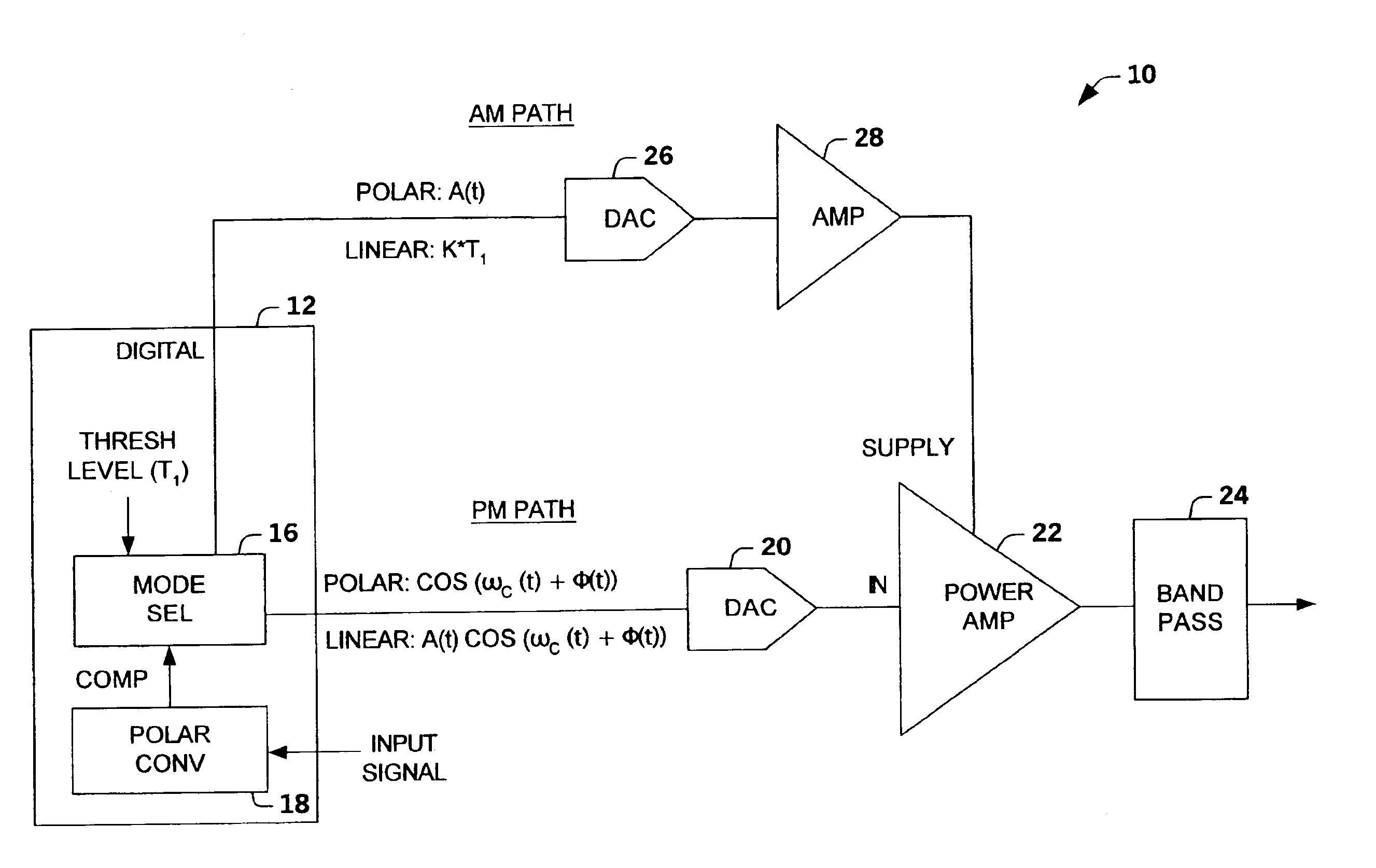
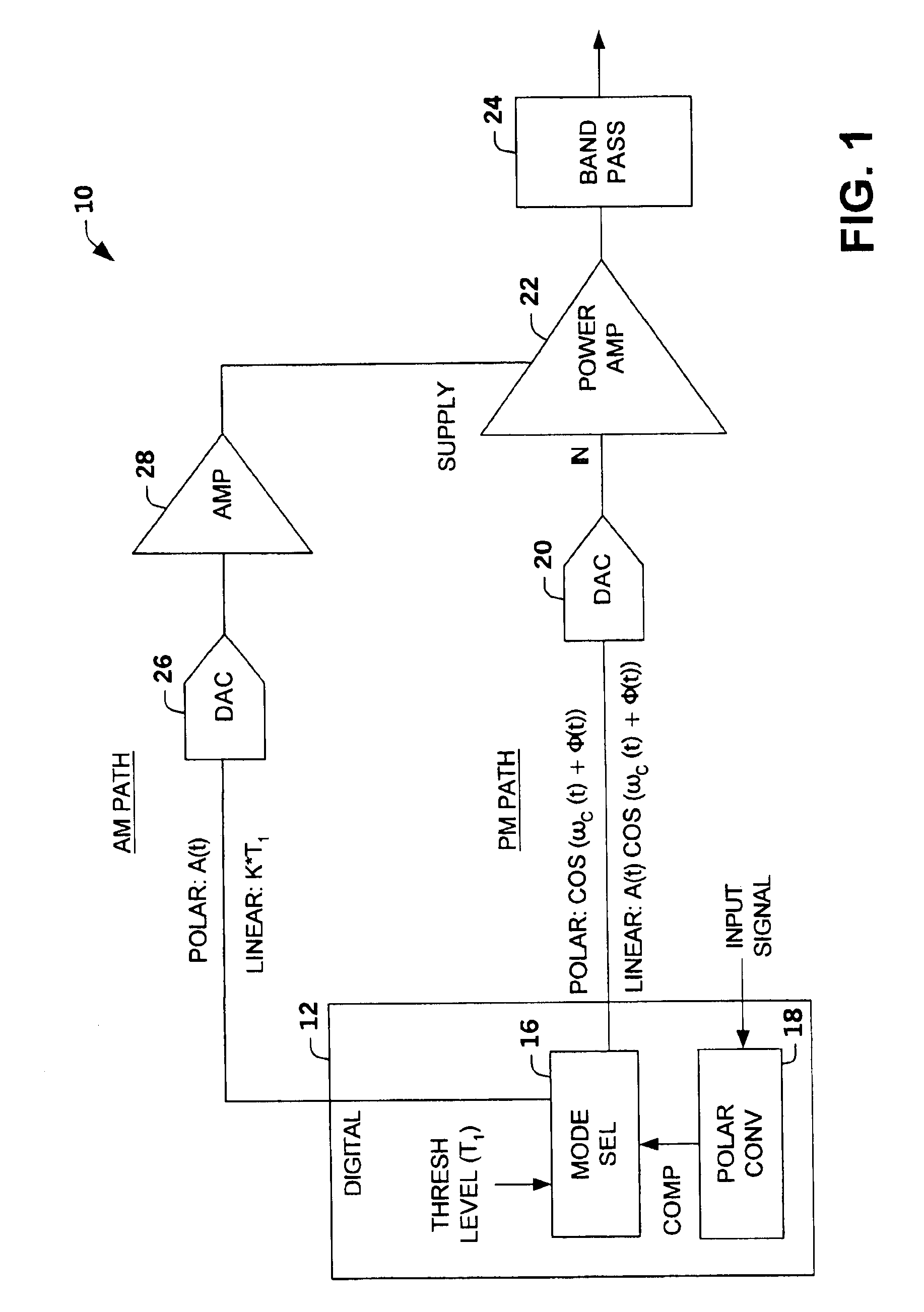
[0022]The present invention relates to an amplifier system that switches modes of operation based on a characteristic of an input signal relative to a threshold level (e.g., envelope amplitude level, digital count representation of signal level, power amplifier power level). The amplifier system operates as a polar amplifier system in a polar mode, and operates as a linear amplifier system (e.g., Class A, A / B, or B) in a linear mode. The amplifier system integrates digital functions with analog components to achieve improved linearity and size reduction of power amplifiers. A mode selector controls whether polar components (“polar mode”) of the signal are sent to a power amplifier or whether the composite signal is amplified (“linear mode”). The amplifier system can employ a power amplifier that maintains a constant class configuration. However, a power amplifier that maintains a constant class configuration is not required.

[0023]The present invention overcomes one or more known obs...


PUM


Abstract

An amplifier system is provided that switches between operation in a polar mode and a linear mode based on a characteristic of an input signal relative to a threshold level. The system operates as a polar amplifier in the polar mode, and as a linear amplifier in the linear mode. A mode selector controls whether polar components of the input signal are sent to a power amplifier or whether a composite signal is amplified.

Description

TECHNICAL FIELD[0001]The present invention relates generally to electronic devices, and more particularly to a polar and linear amplifier system.BACKGROUND OF THE INVENTION[0002]RF power amplifiers used for wireless communication transmitters, with spectrally efficient modulation formats, require high linearity to preserve modulation accuracy and to limit spectral regrowth. Typically, a linear amplifier, Class-A type, Class-AB type or Class-B, is employed to faithfully reproduce inputs signals and to limit the amplifier output within a strict emissions mask. Linear amplifiers are capable of electrical (DC power in to RF power out or DC-RF) efficiencies greater than 50% when operated at saturation. However, they are generally not operated at high efficiency due to the need to provide high linearity. For constant envelope waveforms, linear amplifiers are often operated below saturation to provide for operation in their linear regime. Time varying envelopes present an additional challe...

Claims


Application Information

Patent Timeline
Patent Type & Authority Patents(United States)
IPC IPC(8): H03F3/38H03F1/02H03F1/32H03F3/24H04B1/04
CPCH03F1/0222H03F1/025H03F1/3241H04B2001/045H03F2200/331H04B1/406H03F1/02H03F3/24
Inventor WINTER, FRANKROBINSON, IANDEMORE, WALTER
Owner NORTHROP GRUMMAN SYST CORP
Why Eureka
Try Eureka