
Subsea choke control system

a control system and choke technology, applied in the direction of underwater drilling, wellbore/well accessories, survey, etc., can solve the problems of not all wells producing at the same time, unfavorable production fluid loss, damage to wells and/or reservoirs, etc., to minimize the reaction time of hydraulic signals, reduce the response time of choke actuation, and fast closure and opening

Inactive Publication Date: 2006-01-24
COOPER CAMERON CORP
View PDF18 Cites 48 Cited by
  • Summary
  • Abstract
  • Description
  • Claims
  • Application Information

AI Technical Summary

Benefits of technology

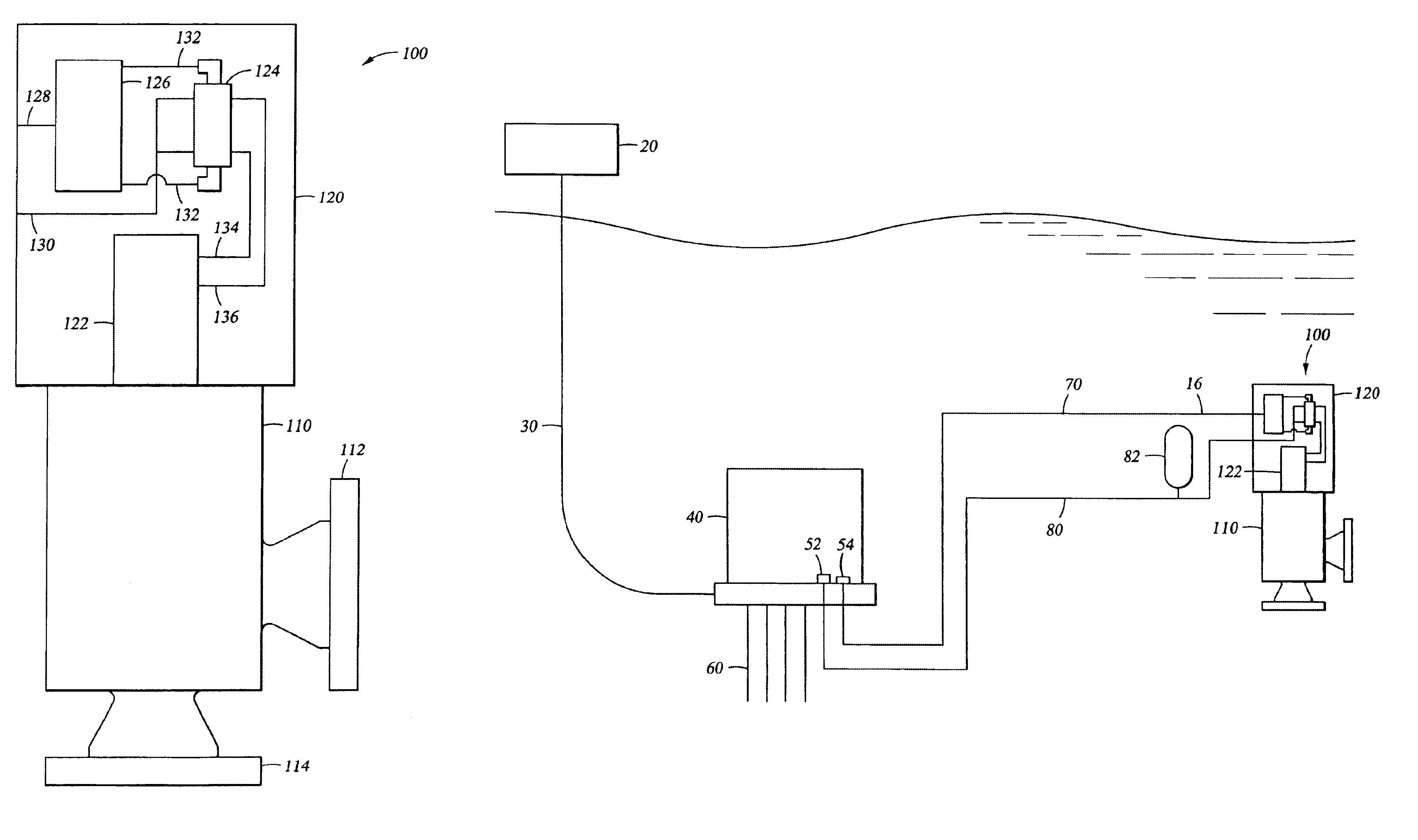
[0010]The preferred embodiments provide a choke or choke actuator having an integrated control system enabling fast closure and opening of the choke. The control system includes integral electronics, such as a valve electronic module, controlling directional control valves and / or solenoid valves, which regulate the flow of hydraulic fluid from a local hydraulic supply to the choke actuator. By locating the control system, directional control valves, and hydraulic supply proximate to the choke actuator, response times for choke actuation are greatly reduced. Additional embodiments may also include other electronic sensing and instrumentation enabling the choke control system to monitor and adjust the choke to maintain selected flow characteristics or in accordance with a predetermined production scheme. Any or all of the components of the choke, the choke control system, or the choke actuator may also be retrievable separately from the other components so as to allow maintenance and replacement.
[0011]In certain embodiments, the choke control system includes one or more valve electronic modules that receive electric signals from the surface along a single, or dual redundant, control line(s). The valve electronic module processes these signals and transmits electrical signals to a directional control valve. The directional control valve includes solenoid valves that, upon receiving a signal from the valve electronic module, actuate to allow hydraulic fluid to flow between a supply and the choke actuator. In the preferred embodiments, the hydraulic supply is located proximate to the choke, such as in an accumulator, so as to minimize the reaction time of the hydraulic signal between the supply and the choke actuator. The choke control system and actuator are preferably integrated into a single package that can be retrieved to the surface for maintenance independent of the choke. Alternatively, the choke control system and actuator can be packaged for separate and / or singular retrieval.
[0012]Incorporating a valve electronic module into the choke control system allows for gains in efficiency in actuating the choke directly from a control system located at the surface, or in actuating the choke from a subsea control module receiving commands from a control system located at the surface. Communication to the choke control system could be provided by hydraulic and electric umbilicals run between the surface control system, or the subsea control module, and the choke control system. The hydraulic and electric signals would merely be commanded by the surface control system or passed along by the subsea control module to the choke control system. Once the electric signal is received by the choke control system, the valve electronic module processes the signal and actuates the directional control valve to open or close the choke as commanded.
[0014]In certain embodiments, the valve electronic module could also provide the choke and choke control system with additional functionality. For example, the valve electronic module may be equipped to monitor pressure transmitters attached to the directional control valve to monitor the application of hydraulic pressure to the actuator. The electronic module may also operate in conjunction with a position measurement sensor to determine the actual position of the choke at any time. The electronic module could also be used to gather data from these and other sensors, such as pressure and / or temperature sensors on the choke inlet and outlet, and transmit this data back to the surface to give the operators an indication of flow conditions at the choke. For example, the use of a venturi, or other geometry change, in conjunction with additional pressure and temperature measurement transmitted to the subsea control module and / or to the surface could enable analytical measurement and determination of flow rates and flow constituency make-up parameters.
[0015]In the preferred embodiments, the improved choke control system allows for significantly increased stepping rates leading to decreased reaction time for choke actuation. Certain embodiments may also provide for increased data acquisition and analysis of flow condition at or near the choke, which could lead to indications of flow characterization and detection of the formation of hydrates.

Problems solved by technology

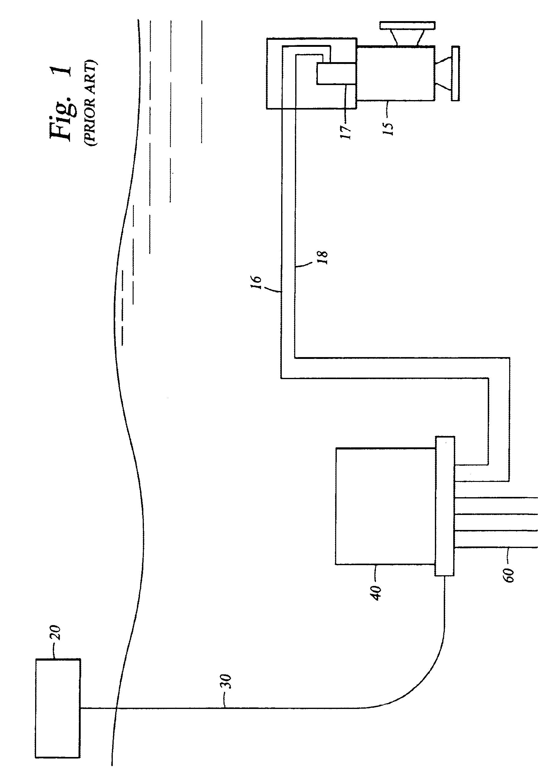
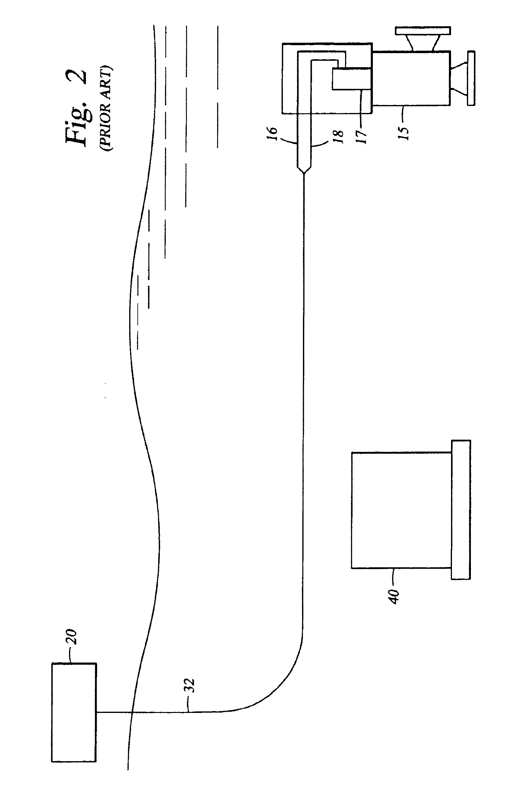
The difficulty in managing a multiple well completion produced through a single flowline is that not all of the wells may be producing at the same pressure conditions or include the same flow constituents (liquids and gases).
Not only is the loss of production fluids undesirable, but the pressure changes and reverse flow conditions within that well may damage the well and / or reservoir.
Similarly, if one well is producing at a pressure above the flowline pressure, that well may produce at an undesirable flow rate and pressure, again with the potential to damage other wells and / or the reservoir.
The risk of equipment failure is also increased due to the components being actuated hundreds, thousands, or even millions, of times.
Also, an additional amount of time is required for the spring to return the actuator to its initial position.
The time to actuate each step can run into minutes, thus, with a total of up to 180 steps required to fully actuate the choke, the time required to fully close or open the choke is considerable.

Method used


Image

  • Subsea choke control system
  • Subsea choke control system
  • Subsea choke control system

Examples


Embodiment Construction

[0010]The preferred embodiments provide a choke or choke actuator having an integrated control system enabling fast closure and opening of the choke. The control system includes integral electronics, such as a valve electronic module, controlling directional control valves and / or solenoid valves, which regulate the flow of hydraulic fluid from a local hydraulic supply to the choke actuator. By locating the control system, directional control valves, and hydraulic supply proximate to the choke actuator, response times for choke actuation are greatly reduced. Additional embodiments may also include other electronic sensing and instrumentation enabling the choke control system to monitor and adjust the choke to maintain selected flow characteristics or in accordance with a predetermined production scheme. Any or all of the components of the choke, the choke control system, or the choke actuator may also be retrievable separately from the other components so as to allow maintenance and ...


PUM


Abstract

A choke actuator having an integrated choke control system enabling fast closure and opening of the choke. The choke control system includes integral electronics to receive signals from a surface or subsea control module and control directional control valves to regulate the flow of hydraulic fluid from a local hydraulic supply to the choke actuator. Response times for choke actuation are greatly reduced by locating the electronic control system and directional control valves in an integrated package with the choke actuator and providing a local hydraulic supply. Additional embodiments may also include other electronic sensing and instrumentation enabling the choke control system to monitor and adjust the choke to maintain selected flow characteristics or in accordance with a predetermined production scheme. Any or all of the components of the choke, the choke control system, or the choke actuator may also be retrievable separately from the other components so as to allow maintenance and replacement.

Description

CROSS-REFERENCE TO RELATED APPLICATIONS[0001]Not applicable.STATEMENT REGARDING FEDERALLY SPONSORED RESEARCH OR DEVELOPMENT[0002]Not applicable.BACKGROUND OF THE INVENTION[0003]The embodiments of the present invention relate generally to methods and apparatus for subsea control systems. More particularly, the embodiments of the present invention relate to control systems for subsea chokes. More particularly, the embodiments of the present invention relate to control systems for improving the response time, controllability, uptime availability, and retrievability of the active components of subsea chokes.[0004]In offshore oil and gas production, it is often common for more than one well to be produced through a single flowline. In a typical installation, the products from each individual well flow are combined into a common flowline, which then carries the products to the surface or combines those products with the products of other flowlines. The difficulty in managing a multiple we...

Claims


Application Information

Patent Timeline
IPC IPC(8): E21B34/00E21B33/035
CPCE21B33/0355E21B34/10E21B34/16E21B47/12E21B47/18
Inventor BODINE, JOHN ERICJAMES, DAVID ANTHONYELLIOTT, DECLAN
Owner COOPER CAMERON CORP
Learn More