Rotor position detection of a switched reluctance drive

a technology of switched reluctance and rotor position detection, which is applied in the direction of coils, synchronous motor starters, ac motor stoppers, etc., can solve the problems of increased assembly cost, potential source of unreliability, and extra electrical connections to the machine, so as to achieve robust and cost-effective

Active Publication Date: 2006-01-24
NIDEC SR DRIVES
View PDF8 Cites 16 Cited by
  • Summary
  • Abstract
  • Description
  • Claims
  • Application Information

AI Technical Summary

Benefits of technology

[0023]Embodiments of the present invention provide a robust and cost-effective method of monitoring rotor position without using a rotor position transducer while being able to operate in the single-pulse mode, with or without continuous current.

Problems solved by technology

However, the rotor position transducer increases the overall cost of assembly, adds extra electrical connections to the machine and is, therefore, a potential source of unreliability.
The storage of this data is a disadvantage as it involves the use of a large memory array and / or additional system overheads for interpolation of data between stored points.
Having to store a two-dimensional array of machine data in order to operate without a position sensor is an obvious disadvantage.
However, in this mode there is no opportunity in the phase cycle to reset the integrators at some known point of zero flux and current, since such a point does not exist.
Nevertheless, a loss of torque is associated with dropping out of continuous current.
However, none of these methods is satisfactory, since the loss of torque can render the machine performance unstable and several cycles are required before stability is reached again because the current must be built up over a period in the continuous current mode.

Method used


Image

  • Rotor position detection of a switched reluctance drive
  • Rotor position detection of a switched reluctance drive
  • Rotor position detection of a switched reluctance drive

Examples


Embodiment Construction

[0035]The phase inductance cycle of a switched reluctance machine is the period of the variation of inductance for the, or each, phase, for example between maxima when the stator poles and the relevant respective rotor poles are fully aligned. The illustrative embodiment to be described uses a 2-phase switched reluctance drive in the motoring mode, but any phase number from one upwards could be used, with the drive in either motoring or generating mode.

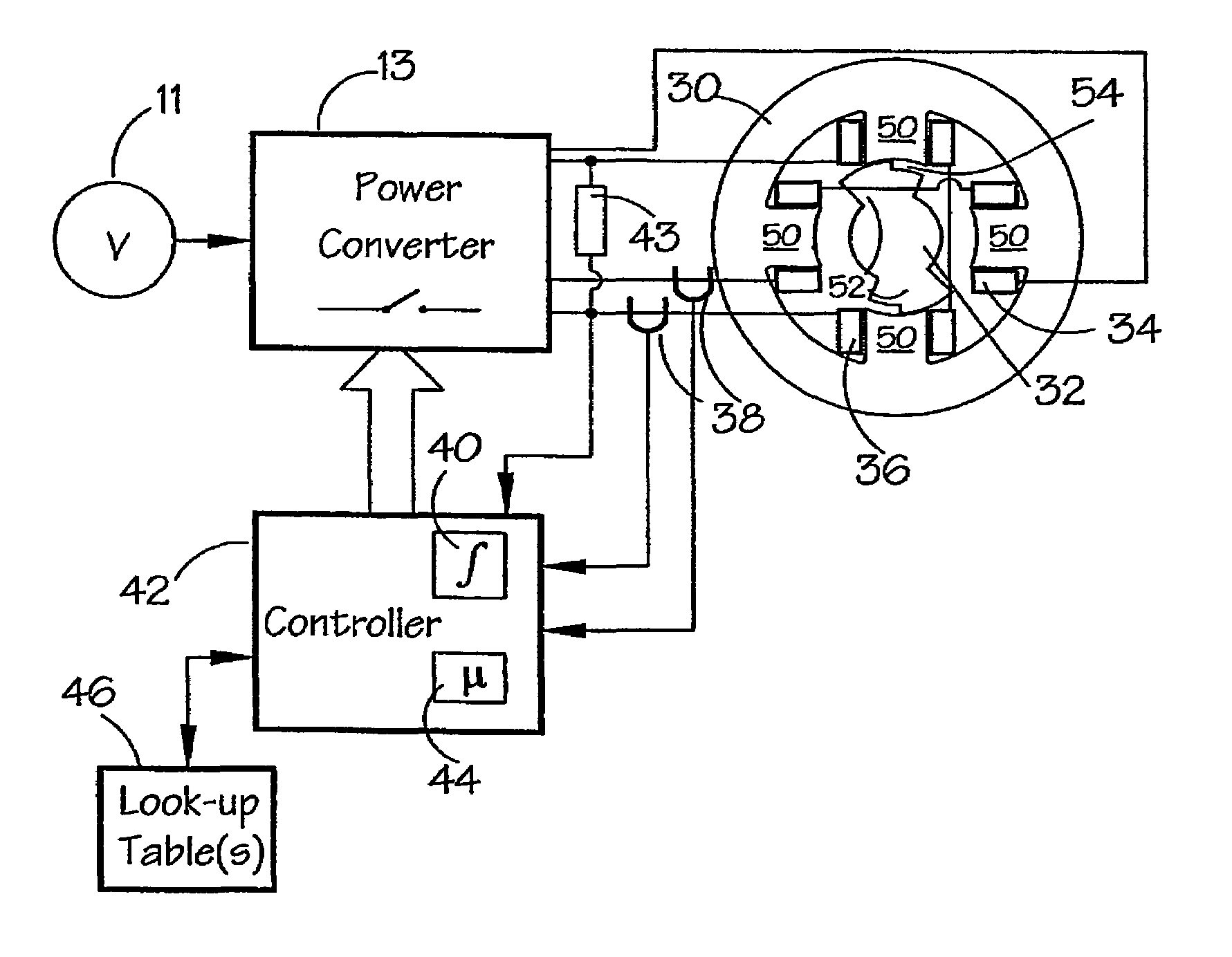
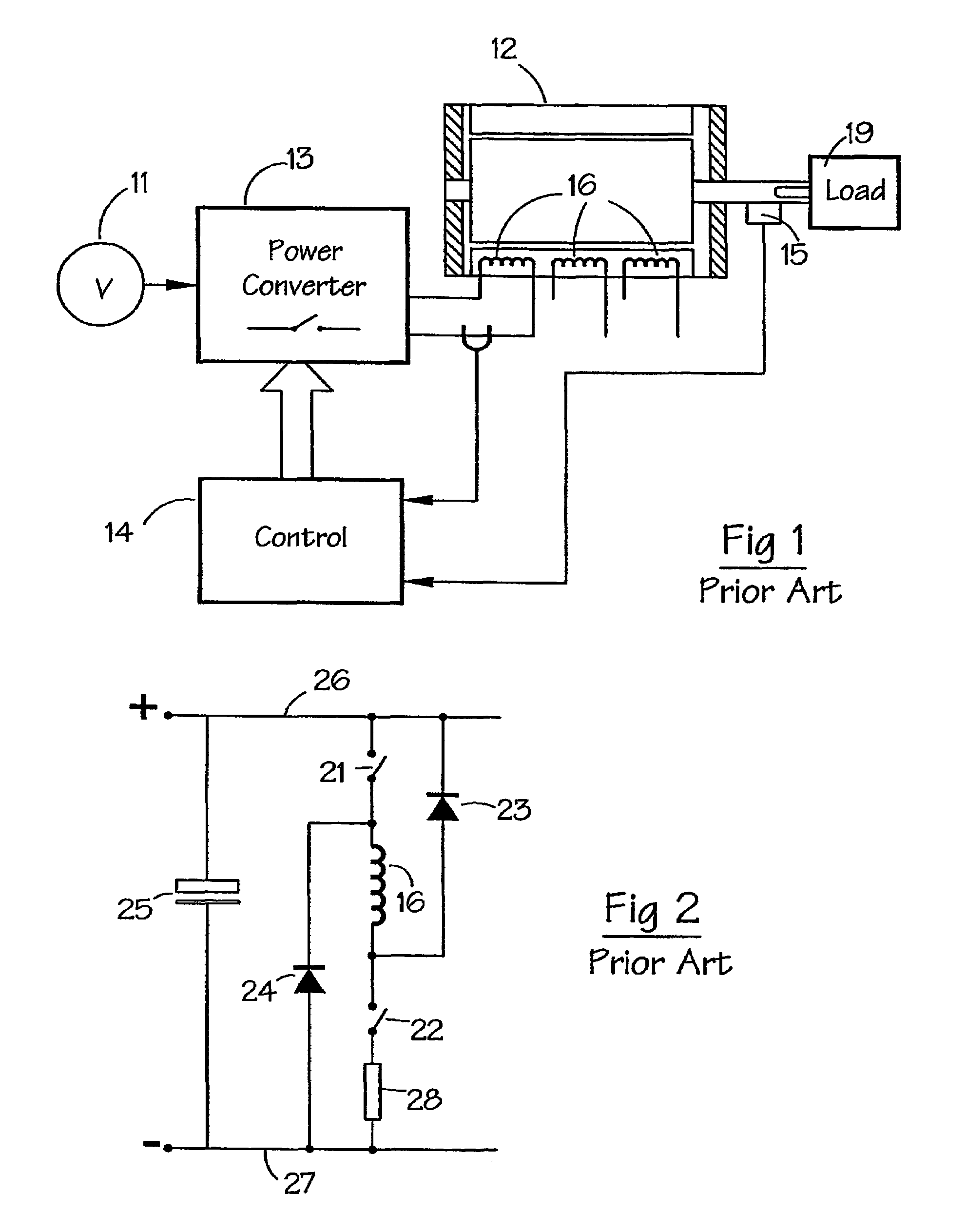
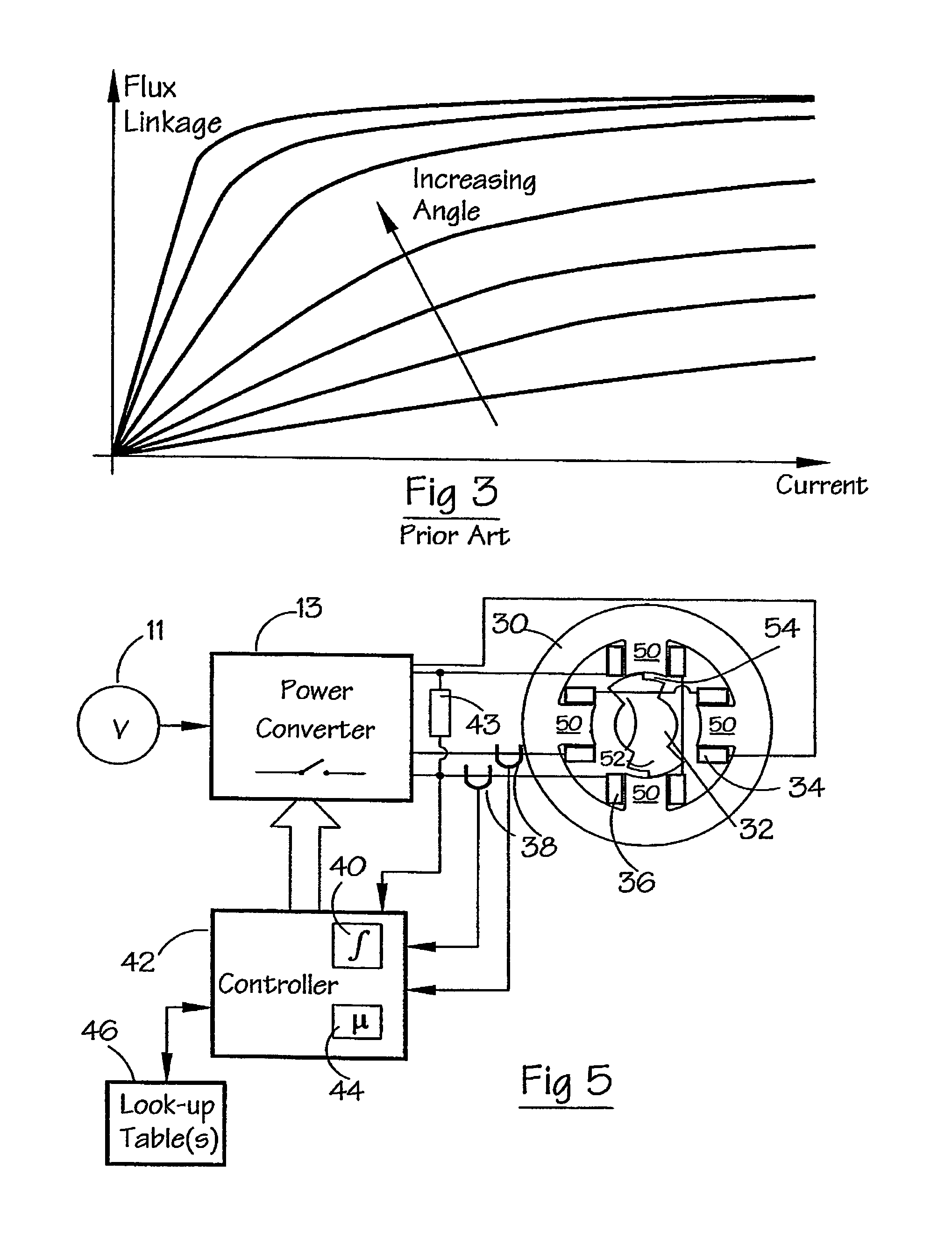
[0036]FIG. 5 shows a system for implementing a method according to an embodiment of the invention. FIG. 6 illustrates graphically a continuous current waveform for the system of FIG. 5. In this system, a power converter 13 is typically the same as that shown in FIG. 1, and like reference numerals have been used where appropriate. The converter 13 controls the switched reluctance machine, as before. The converter 13 is itself controlled by a controller 42 which, in this embodiment, is based on a digital signal processor, e.g. one from ...


PUM


Abstract

A switched reluctance drive is controlled without using a physical rotor position detector. The control method estimates the standing flux-linkage associated with the phase and uses this estimate to improve its subsequent estimate of rotor position. The method works robustly regardless of whether the current is continuous or is discontinuous.

Description

CROSS-REFERENCE TO RELATED APPLICATION[0001]The subject matter of this application is related to the subject matter of British Patent Application No. GB 0312848.5, filed Jun. 4, 2003, priority to which is claimed under 35 U.S.C. § 119 and which is incorporated herein by reference.BACKGROUND OF THE INVENTION[0002]1. Field of the Invention[0003]This invention relates to sensorless rotor position monitoring in reluctance machines, particularly in switched reluctance machines.[0004]2. Description of Related Art[0005]The control and operation of switched reluctance machines generally are described in the paper “The Characteristics, Design and Applications of Switched Reluctance Motors and Drives” by J. M. Stephenson and R. J. Blake, which is incorporated herein by reference, delivered at the PCIM'93 Conference and Exhibition held in Nürnberg, Germany, 21–24 Jun. 1993. In that paper the “chopping” and “single-pulse” modes of energization of switched reluctance machines are described for o...

Claims


Application Information

Patent Timeline
Patent Type & Authority Patents(United States)
IPC IPC(8): G01B7/30H02P1/18H02P25/08H02P6/16
CPCH02P6/18H02P6/16
Inventor MAYES, PETER RICHARD
Owner NIDEC SR DRIVES
Why Eureka
Try Eureka