Satellite antenna station keeping

a satellite antenna and station technology, applied in the direction of radio transmission, electrical equipment, transmission, etc., can solve the problems of communication performance degradation, satellite and earth station communication performance degradation, and the design of the electronic equipment on board a satellite to function for a long tim

Active Publication Date: 2006-01-24
INTELSAT GLOBAL SERVICE
View PDF9 Cites 10 Cited by
  • Summary
  • Abstract
  • Description
  • Claims
  • Application Information

AI Technical Summary

Benefits of technology

[0018]Still another object of the present invention is to provide a technique for satellite antenna beam positioning for a satellite in an inclined orbit which does not require the use of station-keeping fuel.
[0019]It is another object of the present invention to provide a technique for satellite antenna beam positioning for a satellite in an inclined orbit which does not require a beacon signal.
[0020]Yet another object of the present invention is to provide a technique for satellite antenna beam positioning for a satellite in an inclined orbit which provides stable satellite antenna beam coverage over earth stations.

Problems solved by technology

Electronic equipment on board a satellite is designed to function quite a long time.
This movement causes degradations in communications performance between the satellite and the earth station.
This causes communication performance degradation.
Another problem arising from satellite relative position movement is that the satellite's polarization direction at the earth station changes as the satellite's relative position moves.
This also results in the communication performance degradation.
However, polarization direction usually does not cause great performance degradation within a reasonable range of inclination.
This results in changes of the satellite antenna's gain toward the earth station, which also contributes to communication performance degradation.
The movement of the antenna beam pointing position will cause beam coverage on the earth to move accordingly, resulting in a change of the satellite antenna gain toward an earth station, in turn causing communication performance degradation, especially at beam edge.
With a larger ellipse comes an increase in communication performance degradation.
Typically, a loss of 4 or 5 db is unacceptable.
That is, a satellite's signal is not usable due to degradation when the satellite is in a position resulting in such a loss.
This proposed solution requires substantial additional hardware to be installed on-board the satellite which adds weight and complexity to the satellite and also potentially decreases reliability.
However, an even greater problem arises due to the fact that the satellite antenna 120 will necessarily be redirected during the life of the satellite to move the spot beam to different locations on the earth's surface from time to time.
Such movement of the beacon station makes the proposed solution impractical and virtually impossible to implement successfully.

Method used


Image

  • Satellite antenna station keeping
  • Satellite antenna station keeping
  • Satellite antenna station keeping

Examples


Embodiment Construction

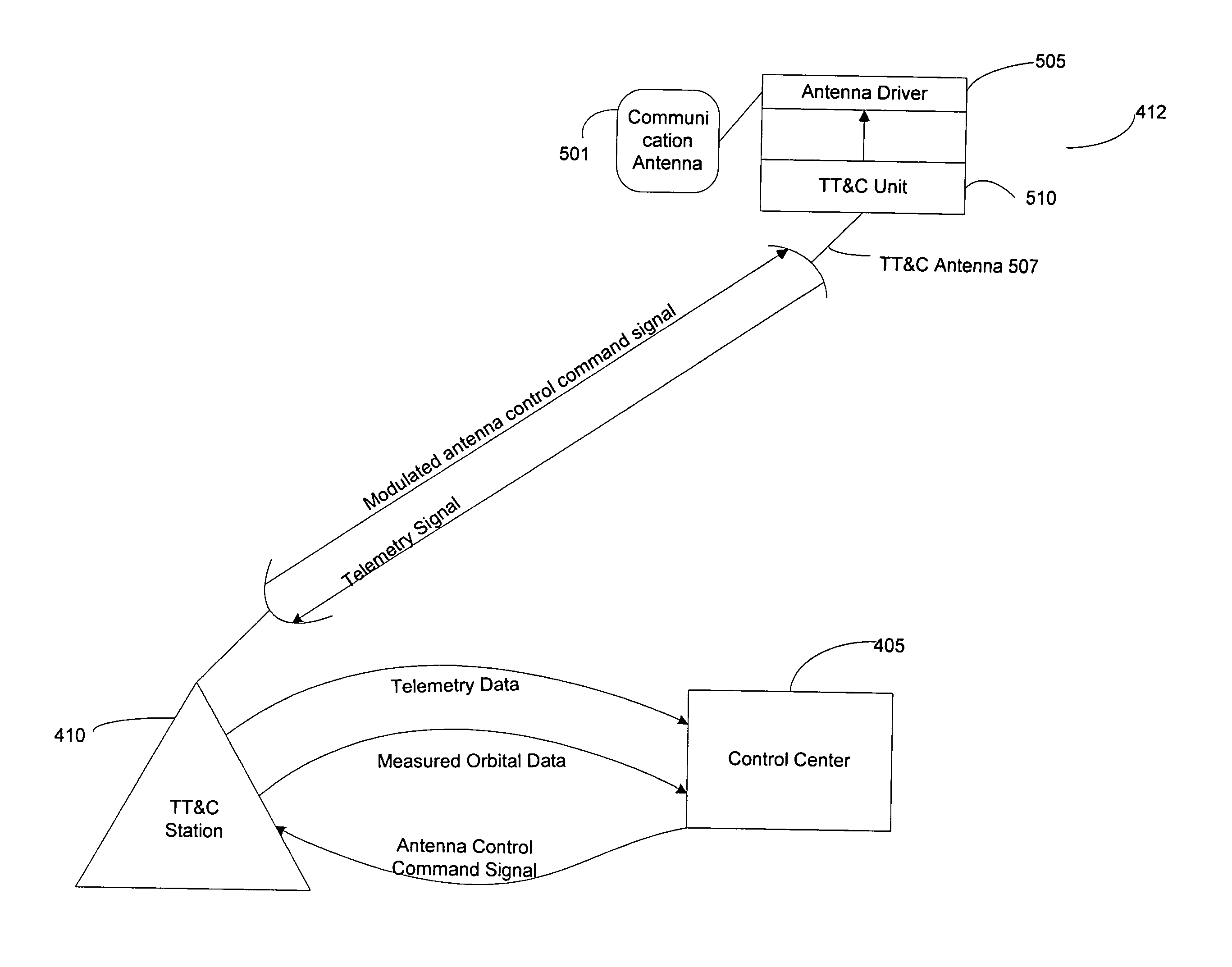
[0055]A new technique of satellite antenna pointing stabilization, called Satellite Antenna Coverage Keeping (SACK), is provided by the present invention for keeping satellite antenna beam pointing close to its nominal beam pointing position on the earth when the satellite is in an inclined orbit, resulting in keeping antenna coverage on the earth stable. SACK compensates for the beam pointing deviation caused mainly by satellite inclination. FIG. 4 shows a simplified overview block diagram of SACK implementation.

[0056]A SACK program 401 receives satellite data from a Satellite Control Center 405. The received data includes Intelsat Eleven Parameter Satellite Ephemeris or other type of satellite orbit elements; satellite attitude data (Time, Roll, Yaw and Pitch angles); antenna nominal beam pointing position on the earth (latitude and longitude) or on satellite (azimuth and elevation). The SACK program 401 generates antenna beam pointing maneuver data using the received data and tra...


PUM


Abstract

Techniques for redirecting a satellite antenna beam from a satellite antenna of a satellite in an inclined orbit to a preferred satellite antenna beam pointing position on the earth are provided. Satellite antenna maneuver data is computed based upon information associated with the satellite, such as telemetry, orbital, and antenna nominal pointing information. Command code sequences are then generated that correspond to the maneuver data. The command codes are executable at the inclined orbit satellite to modify the antenna position. The generated command codes are then transmitted to the inclined orbit satellite to redirect the satellite antenna beam center to the preferred position.

Description

FIELD OF THE INVENTION[0001]The present invention is related to satellite antenna beam positioning, and more particularly to satellite antenna beam positioning to compensate for satellite antenna pointing deviation on the earth resulting from a satellite in an inclined orbit.BACKGROUND OF THE INVENTION[0002]During optimal operation a satellite antenna beam center or pointing position on the earth is kept within a small box in both directions of North-South and East-West around its nominal position. When a beam center position is within this optimal box, the beam coverage on the earth is stable, communications between the earth station and the satellite are stable and earth station antennas do not have to be often repositioned for tracking the satellite to maintain stable communications.[0003]Electronic equipment on board a satellite is designed to function quite a long time. Thus, the determining factor of a satellite's operational lifespan is not electronic equipment life, but rath...

Claims


Application Information

Patent Timeline
Patent Type & Authority Patents(United States)
IPC IPC(8): H04B7/185
CPCH04B7/18515
Inventor DONG, GUIBIN
Owner INTELSAT GLOBAL SERVICE
Why Eureka
Try Eureka