In-situ cleaning of beam defining apertures in an ion implanter

a beam defining aperture and ion implantation technology, which is applied in the field of ion implantation systems, can solve the problems of reducing the efficiency and product affecting the efficiency and yield of so as to prevent contaminants from contaminating other components and limit the amount of cross-contamination within the ion implantation system

Active Publication Date: 2006-01-31
AXCELIS TECHNOLOGIES
View PDF7 Cites 43 Cited by
  • Summary
  • Abstract
  • Description
  • Claims
  • Application Information

AI Technical Summary

Benefits of technology

[0012]According to another exemplary aspect of the invention, a barrier is placed in a path of the ion beam prior to the modulation of the extraction voltage, wherein the barrier is placed generally downstream from the one or more components. For example, the barrier comprises a flag Faraday positioned downstream from the resolving plate, or a Faraday cup positing within an end station of the ion implantation system. The barrier generally collects the one or more contaminants removed from the one or more components during the subsequent extraction voltage modulation, thus generally containing the contaminants and generally preventing the contaminants from contaminating other components of the ion implantation system.
[0013]In accordance with yet another exemplary aspect of the present invention, the one or more components comprise a resolving plate having an aperture therethough defining at least a first surface. An upstream facing surface of the resolving plate is further generally defined by a second surface obliquely oriented with respect to the ion beam, wherein at least some of the one or more contaminants are disposed on the second surface. Upon modulation of the extraction voltage, the ion beam is generally swept across at least the upstream facing surface of the aperture, therein rapidly thermally cycling one or more of the contaminants and the aperture, thus generally dislodging the one or more contaminants from the aperture. The dislodged contaminants, for example, are then collected by the barrier, thus limiting an amount of cross-contamination within the ion implantation system.

Problems solved by technology

Such contamination of the workpiece 30 may lead to a failure of the resulting device(s) (not shown) formed on the workpiece, thus decreasing the efficiency and product yield of the ion implantation system 10.
Such wafers are expensive and, thus, make it very desirable to mitigate waste, such as having to scrap an entire wafer due to contaminants imparted to the wafer during ion implantation.
Such manual cleaning is costly, not only in terms of time and labor attributed to the operator, but also in terms of decreased efficiency and yield of the ion implantation system 10 due to increased down-time associated with the maintenance.
Such a change of gases, however, may decrease the efficiency of the ion implantation system 10, thus decreasing a throughput of the implanter.

Method used


Image

  • In-situ cleaning of beam defining apertures in an ion implanter
  • In-situ cleaning of beam defining apertures in an ion implanter
  • In-situ cleaning of beam defining apertures in an ion implanter

Examples


Embodiment Construction

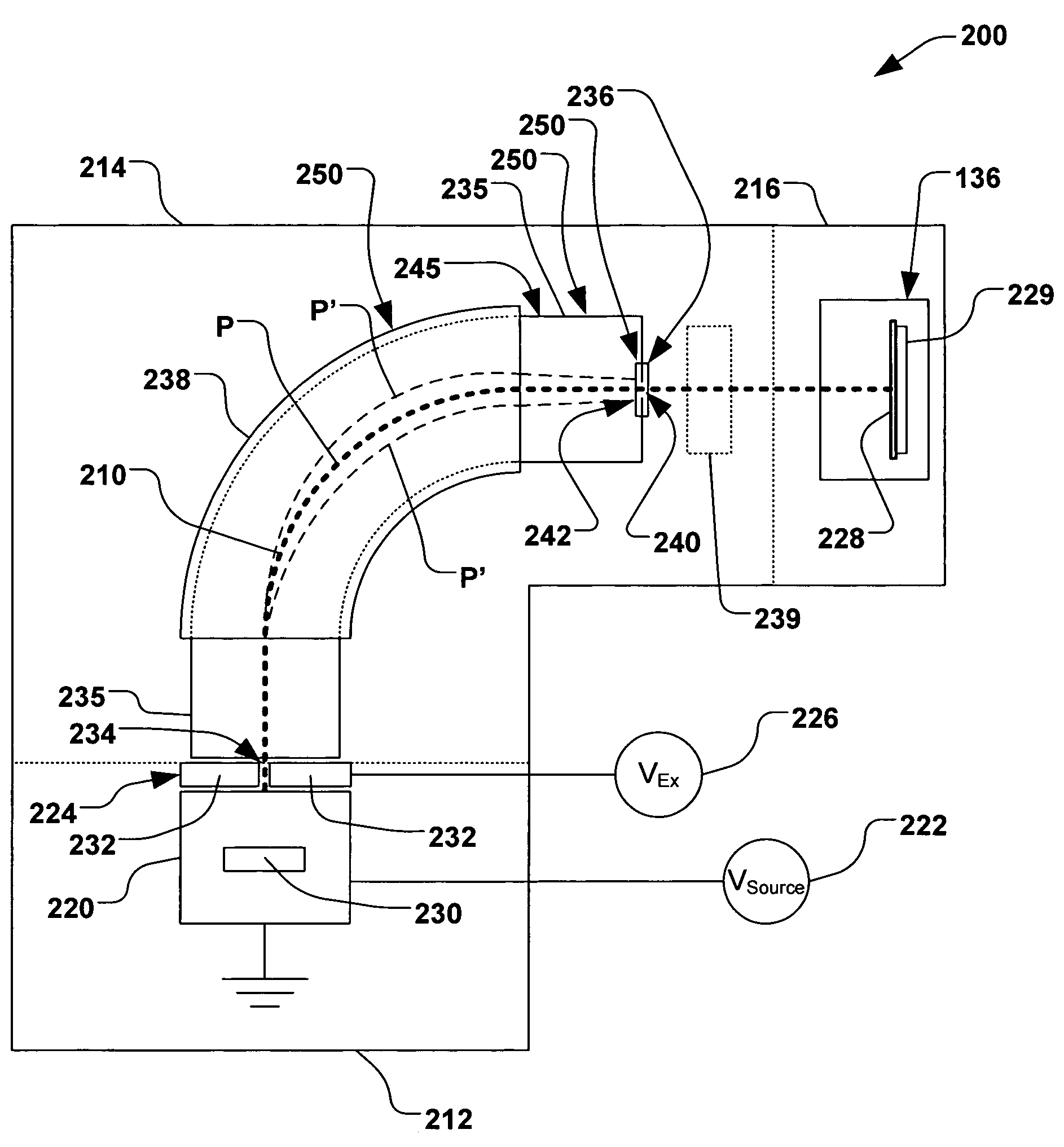
[0022]The present invention is directed generally towards a system and method for cleaning beam defining devices in an ion implantation system. More particularly, the method provides an in-situ cleaning of a beam defining aperture using an ion species that is also used for ion implantation into a workpiece. Accordingly, the present invention will now be described with reference to the drawings, wherein like reference numerals are used to refer to like elements throughout. It should be understood that the description of these aspects are merely illustrative and that they should not be taken in a limiting sense. In the following description, for purposes of explanation, numerous specific details are set forth in order to provide a thorough understanding of the present invention. It will be evident to one skilled in the art, however, that the present invention may be practiced without these specific details.

[0023]Referring now to the figures, FIG. 2 illustrates an exemplary ion implant...


PUM


Abstract

A method for cleaning an ion implantation, comprising providing an ion implantation system, wherein the ion implantation system comprises one or more components having one or more contaminants disposed thereon. A process species is provided to the ion implantation system, wherein the process species is otherwise utilized to implant ions into a workpiece. Ions are formed from the process species, therein defining an ion source. An ion beam is then extracted from the ion source via an application of an extraction voltage to an ion extraction assembly associated with the ion source. The extraction voltage is further modulated, wherein a trajectory of the ion beam is oscillated within a predetermined range. The ion beam is consequently swept across the one or more components, thus substantially removing the one or more contaminants therefrom.

Description

FIELD OF THE INVENTION[0001]The present invention relates generally to ion implantation systems, and more specifically to systems and methods for cleaning one or more beam defining devices in an ion implantation system.BACKGROUND OF THE INVENTION[0002]In the manufacture of semiconductor devices and other products, ion implantation systems are used to impart impurities, known as dopant elements, into semiconductor wafers, display panels, or other workpieces. Typical ion implantation systems or ion implanters treat a workpiece with an ion beam in order to produce n- or p-type doped regions, or to form passivation layers in the workpiece. When used for doping semiconductors, the ion implantation system injects a selected ion species to produce the desired extrinsic material. For example, implanting ions generated from source materials such as antimony, arsenic, or phosphorus results in n-type extrinsic material wafers. Alternatively, implanting ions generated from materials such as bor...

Claims


Application Information

Patent Timeline
Patent Type & Authority Patents(United States)
IPC IPC(8): H01J37/317H01J37/36
CPCH01J37/3171H01J2237/022
Inventor RING, PHILIP J.PEREL, ALEXANDER S.
Owner AXCELIS TECHNOLOGIES
Why Eureka
Try Eureka