Leak check device for evaporated fuel purging system

a technology of leak detection and purging system, which is applied in the direction of fluid tightness measurement, electrical control, instruments, etc., can solve the problems of reducing the effect of preventing the emission of evaporated fuel cannot be sufficiently achieved, and the output characteristics of the motor unit can be reduced, so as to improve the accuracy of leak detection for inspecting the state of leakag

Active Publication Date: 2006-02-07
DENSO CORP
View PDF6 Cites 25 Cited by
  • Summary
  • Abstract
  • Description
  • Claims
  • Application Information

AI Technical Summary

Benefits of technology

[0014]The object of the present invention is to provide a leak check device for evaporated fuel purging system which checks a leak by applying or reducing pressure by a motor pump so that the accuracy of leak detection can be enhanced.
[0017]The motor unit which drives the pump for pressurizing or depressurizing the evaporated fuel purge system for leak check is fed with input voltage obtained by converting the battery voltage into a predetermined voltage through the voltage control circuit. Even if the battery voltage fluctuates, therefore, the input voltage can be set to, for example, a predetermined voltage within a voltage range in which the battery voltage fluctuates. Thus, variation in the output characteristics of the motor unit and variation in the pump power of the pump driven by the motor unit due to fluctuation in battery voltage can be reduced. As a result, the accuracy of leak detection for inspecting the state of leakage can be enhanced.

Problems solved by technology

However, when a crack or the like exists in a pipe or container constituting an evaporated fuel recovery path running from the fuel tank to the purge control valve through the canister, the evaporated fuel leaks to the outside and the effect of preventing the emission of evaporated fuel cannot be sufficiently attained.
A reference leak is caused by the motor pump with pressure as a result of changing the flow path by the switchover valve.
The above prior arts are not satisfactory.
As a result, the accuracy of leak detection for determining in which state of leakage the size of a leaking hole determined from internal pressure change in section D is can be impaired.
Therefore, it is likely that a relief valve for failsafe is opened before a desired reference pressure is reached.
When the setting of valve opening pressure for the relief valve is increased, the pump power is excessively increased and the fuel tank is overloaded.
For the above reasons, it is difficult to enhance the accuracy of leak detection with the above prior arts.
Therefore, there is a possibility that the leakage reference values established by CARB and EPA or stricter leakage reference values in the future cannot be met.

Method used


Image

  • Leak check device for evaporated fuel purging system
  • Leak check device for evaporated fuel purging system
  • Leak check device for evaporated fuel purging system

Examples


first embodiment

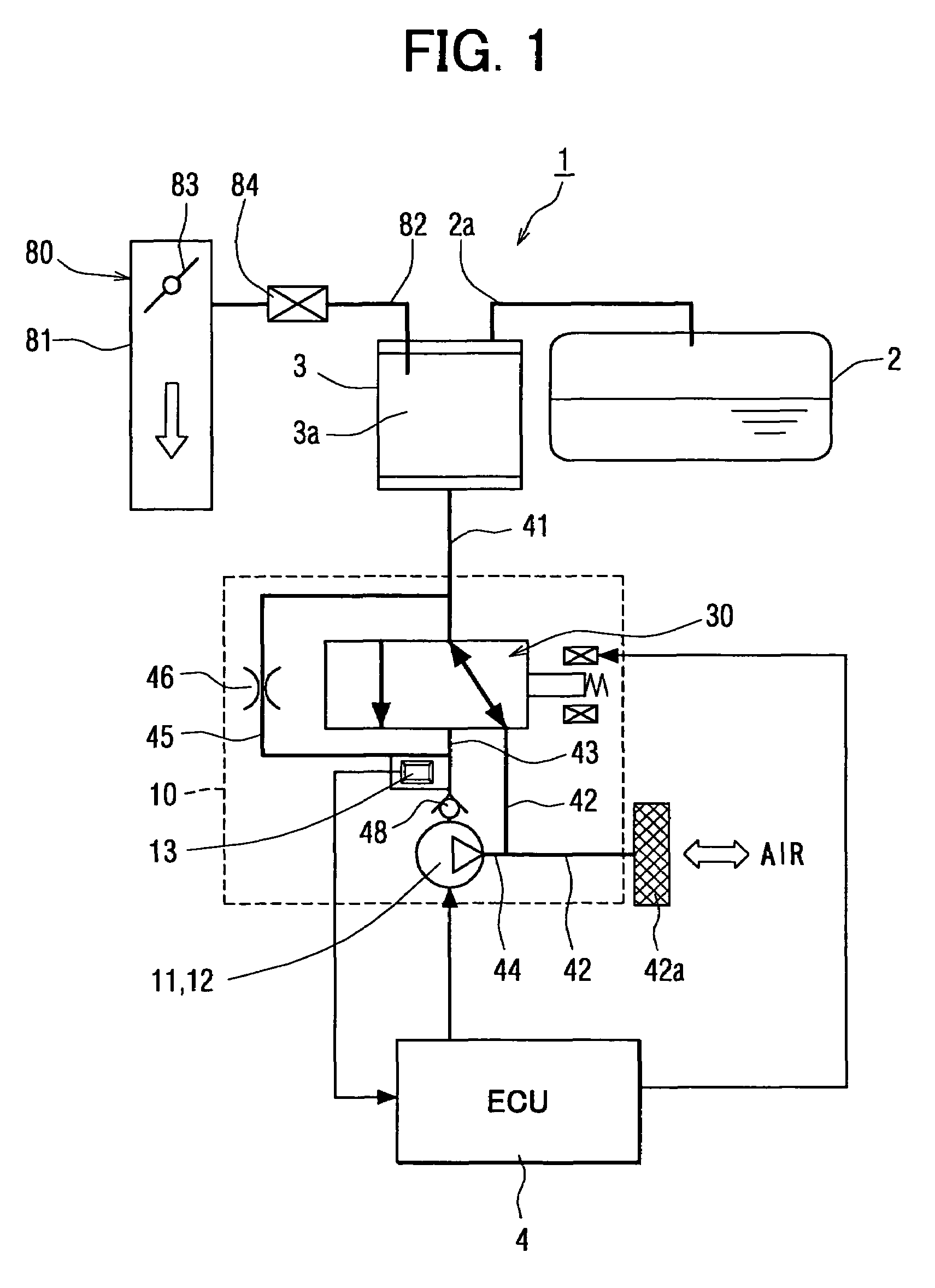
[0032]As illustrated in FIG. 1, an evaporated fuel purging system comprises a fuel tank 2, a canister 3 as an adsorption filter which is connected with the fuel tank 2 through a connecting flow path 2a and has a venting flow path 41, and a purge control valve 84 as a vent valve. One end of the vent valve 84 connects to the canister 3 through a valve flow path 82 and the other end of the same connects to the intake system 80 of an internal combustion engine through the valve flow path 82. The canister 3 contains adsorbent 3a such as activated carbon.

[0033]Part of fuel retained in the fuel tank 2 is evaporated, and evaporated fuel is produced in the fuel tank 2. The evaporated fuel is guided into the canister 3 and temporarily adsorbed and accumulated therein. When the purge control valve 84 is opened by air with reduced pressure in the intake system 80, air is taken in through an open flow path 42, the canister 3, and the valve flow path 82. At the same time, the evaporated fuel accu...

fifth embodiments

Second to Fifth Embodiments

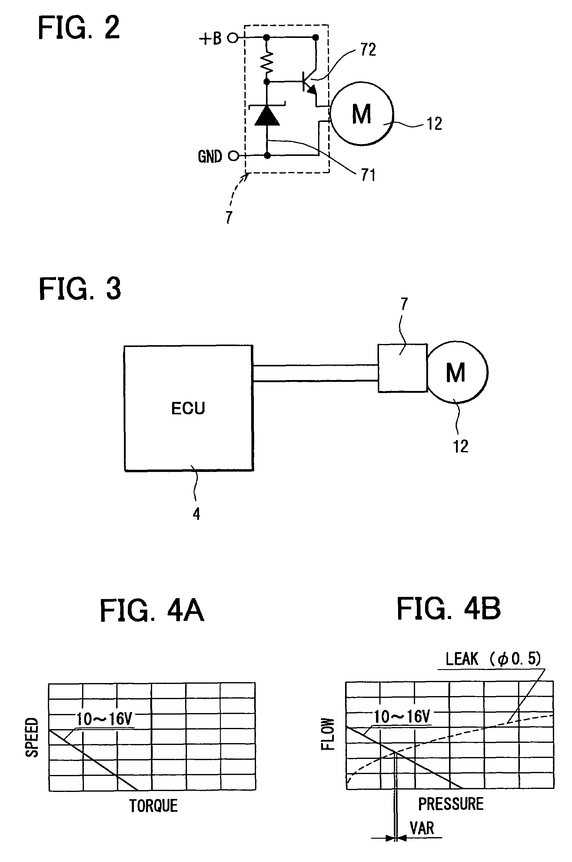
[0088]As described above, in the first embodiment, the constant voltage circuit 7 is connected to the input stage of the motor unit 12 for controlling the input voltage which supplies the motor unit 12 with a current to the predetermined voltage. In the second embodiment, the constant voltage circuit 7 is connected to the motor drive IC 5 of the motor unit 12 instead, as illustrated in FIG. 5. Thus, as a motor unit 12 for driving the pump 12, a brushless motor which has no electrical contacts and has no slidable contact portions can be used. The motor unit 12 may be a DC motor or a brushless motor having the motor drive IC 5. In either case, input voltage which supplies the motor unit 12 with a current can be controlled by the constant voltage circuit 7. Even if evaporated fuel from the evaporated fuel purge system 1 sweeps through the canister 3 and enters the pump 11 and the motor unit 12, local wear is prevented, and the life of the leak check device ca...

sixth embodiment

[0093]In the six embodiment, of the constituent members of the leak check device described as the first embodiment, those disposed in the dotted line in FIG. 1 are integrally assembled into a module. Specifically, the leak check module 10 is constructed as illustrated in FIG. 9. The leak check module 10 comprises a housing 20, a pump 11, a motor unit 12, a switchover valve 30 and a pressure sensor 13.

[0094]The housing 20 houses the pump 11, motor unit 12 and switchover valve 30. The housing 20 comprises a pump chamber 21 for housing the pump 11 and a valve chamber 22 for housing the switchover valve 30. The housing 20 further comprises a venting flow path 41, an open flow path 42, a valve-connecting flow path 43, an exhaust flow path 44 and a reference channel 45. The venting flow path 41 runs from the valve chamber 22 in the housing 20 to the fuel tank 2 by way of the canister 3. The open flow path 42 runs from the valve chamber 22 to the open end 42a. The valve-connecting flow pat...


PUM


Abstract

An evaporated fuel purge system has a fuel tank, an adsorption filter and a purge control valve. The evaporated fuel purge system is pressurized and depressurized through a venting flow path by a pump, so that the state of leakage therefrom is thereby inspected. For this inspection, a motor unit for driving the pump which applies or reduces pressure, an in-vehicle battery and a voltage control circuit which controls a battery voltage to a predetermined voltage and supplies the motor unit with a current are provided. A switchover valve is integrated with the pump, the motor and the like into a single module.

Description

CROSS REFERENCE TO RELATED APPLICATION[0001]This application is based on and incorporates herein by reference Japanese Patent Application No. 2003-20503 filed on Jan. 29, 2003.FIELD OF THE INVENTION[0002]The present invention relates to a leak check device for evaporated fuel purging system.BACKGROUND OF THE INVENTION[0003]An evaporated fuel purging system includes, for example, a fuel tank of an internal combustion engine, a canister, and a purge control valve. This evaporated fuel purging system is so designed that evaporated fuel produced in the fuel tank is temporarily adsorbed to the canister. The evaporated fuel adsorbed to the canister is taken, together with fresh air introduced through the fresh air inlet in the canister, into the air intake system of the internal combustion engine through the purge control valve. However, when a crack or the like exists in a pipe or container constituting an evaporated fuel recovery path running from the fuel tank to the purge control valv...

Claims


Application Information

Patent Timeline
Patent Type & Authority Patents(United States)
IPC IPC(8): G01M3/04G01M3/26F02D45/00F02M25/08G01M3/02G01M3/40G01M15/00G01M15/04
CPCF02M25/0818F02D2200/503F02M25/0827
Inventor KANO, MASAOYAMADA, YOSHICHIKAKOBAYASHI, MITSUYUKIINAGAKI, KOICHI
Owner DENSO CORP
Why Eureka
Try Eureka