
Modular system for storing gas cylinders

a module system and gas cylinder technology, applied in the direction of transportation items, non-pressure vessels, liquefaction, etc., can solve the problems of large space occupation of small amount of gas, high capital cost, and inability to store material at that volume. , to achieve the effect of increasing the size of the present invention and high capital cos

Inactive Publication Date: 2006-02-07
ENERSEA TRANSPORT
View PDF34 Cites 55 Cited by
  • Summary
  • Abstract
  • Description
  • Claims
  • Application Information

AI Technical Summary

Benefits of technology

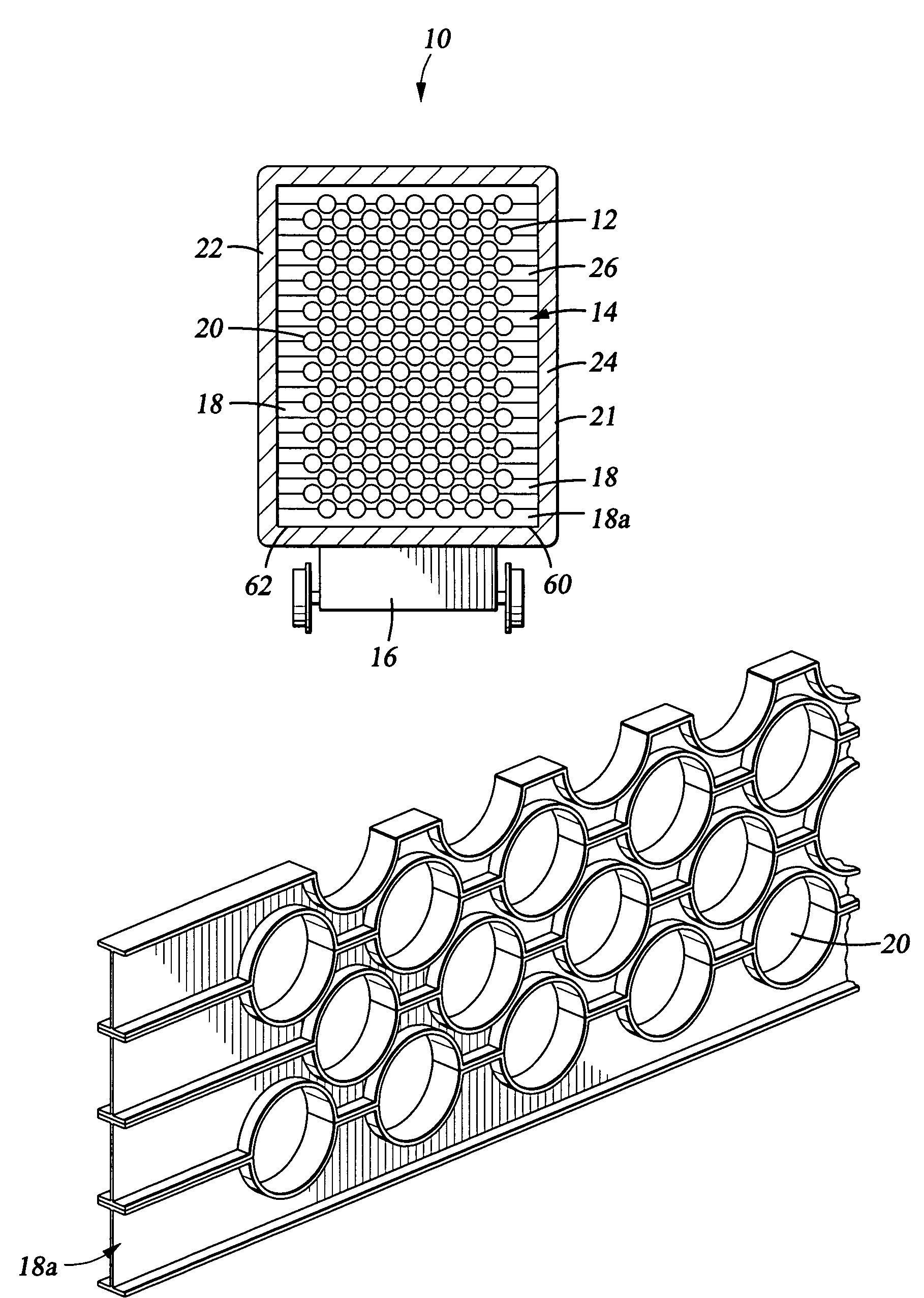
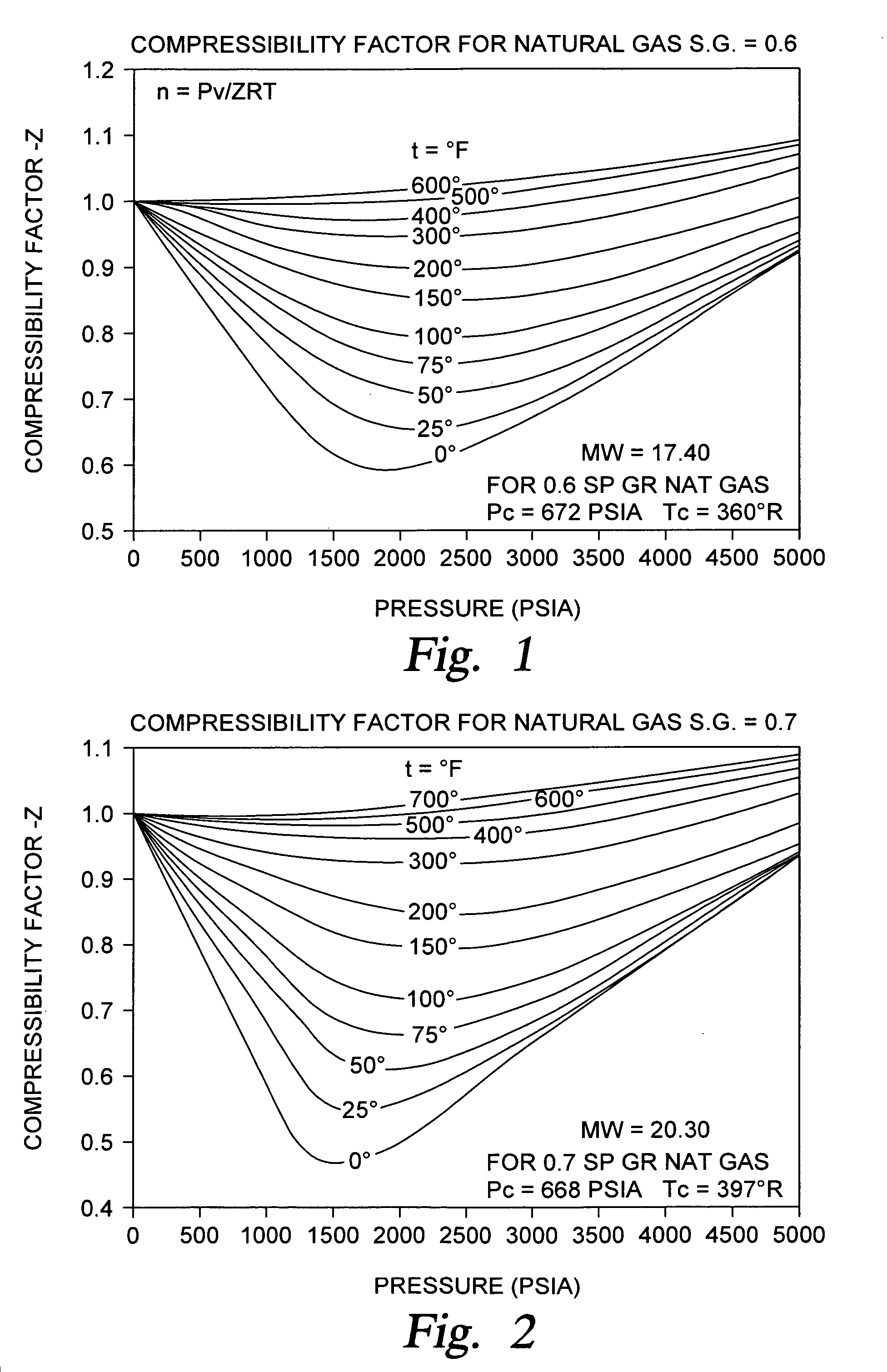
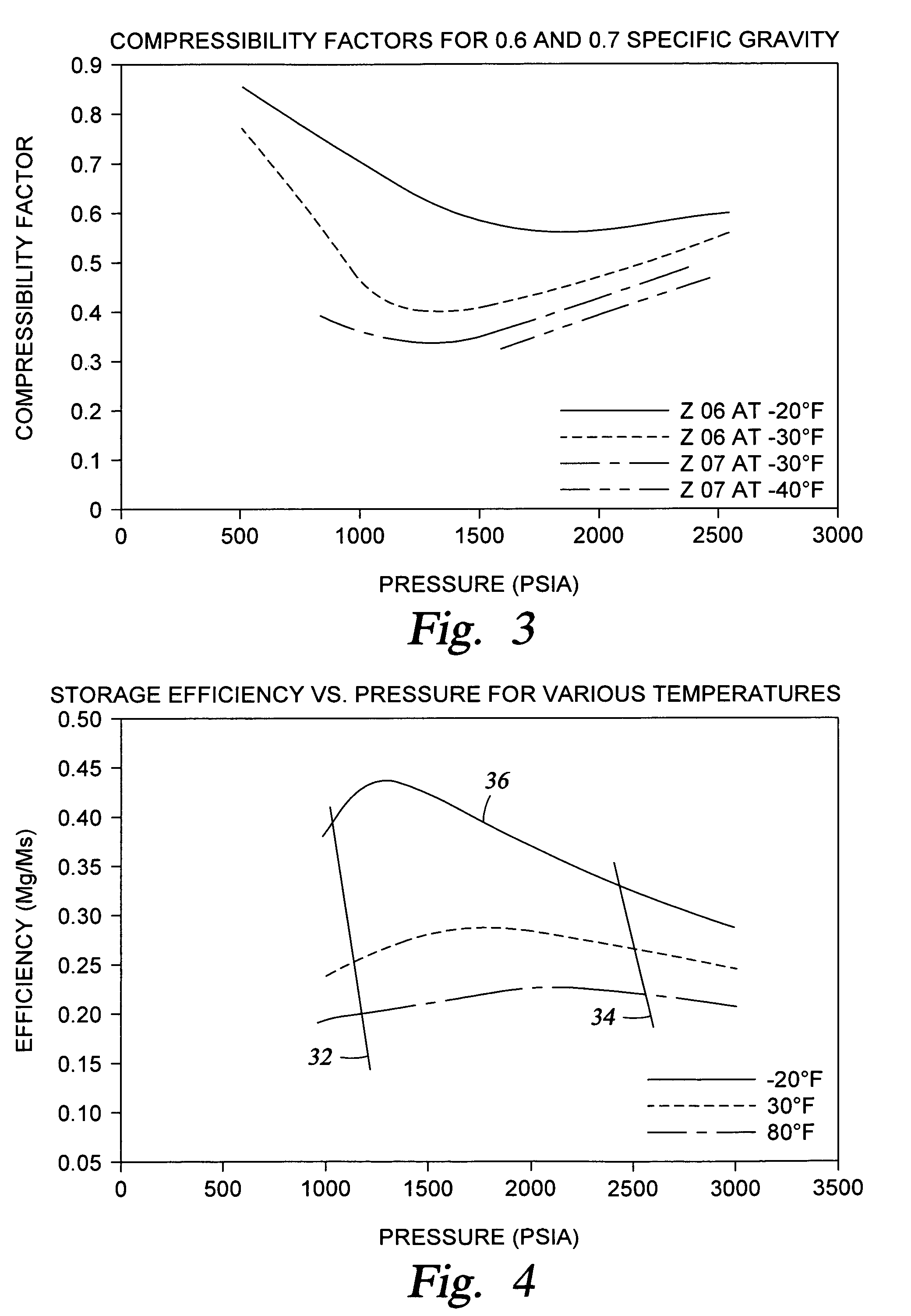
"The present invention is about a gas storage system and methods for transporting and storing compressed gas. The system is designed to optimize the storage and transport of gas by using a containerized system that can be transported on a vehicle. The system includes a gas storage system that is independent of the vehicle's structure. The gas is stored in a nitrogen-rich environment to maximize the compression ratio of the gas. The system also includes a gas storage system that is designed for a specific gas composition and can be optimized for the compressibility factor of the gas. The system can also use premium pipe manufactured to high standards for pressure vessels to minimize the weight of the steel per unit weight of stored gas. The system can also include staged off-loading using low freezing point liquid and liquid driven pigs to separate the gas from the liquid. The invention provides many unique features such as a containerized system, staged off-loading, and matching of gas storage pipe dimensions to the optimized compressibility factor of the gas supply."

Problems solved by technology

The most readily apparent problem with gas storage and transportation is that in the gas phase, even below ambient temperature, a small amount of gas occupies a large amount of space.
Storing material at that volume is often not economically feasible.
Although liquefaction would seem a solution to the storage and transportation problems, the drawbacks quickly become apparent.
Cryogenic process requires a large initial cost for LNG facilities at both the loading and unloading ports.
The containment systems and storage vessels require exotic metals to hold LNG at −260° F. Liquefied natural gas can also be stored at higher temperatures than −260° F. by raising the pressure but, unless temperatures are kept relatively low, the efficiency of the storage system will quickly deteriorate.
Therefore, although the storage temperature may be above −260° F., cryogenic problems still remain and the containment systems now must be pressure vessels.
This may not be an economical alternative.
Compressors are expensive and increase the capital cost of the unloading facilities.
The higher temperature increases the required storage volume unless the heat is removed, or excess gas removed, and raises the overall cost of transporting the CNG.
Previous efforts to reduce the expense and complexity of unloading CNG, and the residual gas in particular, have introduced problems of their own.
Further, the design of the piping and valve arrangements for such a system is necessarily extremely complex because the system must accommodate the introduction of heating devices or heating elements into the storage containers.
In summary, although CNG transportation and storage reduces the capital costs associated with LNG, the costs are still high due to a lack of efficiency by the methods and apparatus used.
This is due primarily to the fact that prior art methods do not optimize the vessels and facilities for a particular gas composition.
In particular, prior art apparatus and methods are not designed based upon a specific composition of gas to determine the optimum storage conditions for that particular gas.
However, there is no consideration of a pipe design factor and no attempt is made to utilize the maximum compressibility factor for the gas.
This would be particularly true when operated at a lower pressure causing the pipe to be over designed (unnecessarily thick).
However, the '725 patent does not design its method and apparatus by optimizing the compressibility factor at a certain temperature and pressure and then calculating the wall thickness for the storage container needed for a certain gas.
Since much of the capital cost comes from the large amount of metal, or other material, required for the pipe storage components, the '725 misses the mark.
It also does not consider onshore storage and thermal shock.
Another problem in the energy industry relates to gas storage and occurs during “peak shaving.” Energy consumption by consumers is not constant over time and there are periods when there is a greater demand for energy than other periods, particularly during the work day when energy consumption is higher due to industry and business operations and particularly when the temperature during the day is at its highest requiring additional energy due to the widespread operation of air conditioning.
Thus power companies pay for this excess capacity without regard to peak periods of demand which is expensive.
Of course, it is not cost effective to run a pipeline to the rig for the gas until the well has been tested to ensure enough gas is being produced to warrant a pipeline.

Method used


Image

  • Modular system for storing gas cylinders
  • Modular system for storing gas cylinders
  • Modular system for storing gas cylinders

Examples


Embodiment Construction

[0075]In the description which follows, like parts are marked throughout the specification and drawings with the same reference numerals, respectively. The drawing figures are not necessarily to scale. Certain features of the preferred embodiments may be shown in exaggerated scale or in somewhat schematic form and some details of conventional elements may not be shown in the interest of clarity and conciseness. It is understood that the systems disclosed in this application are intended to be designed in accordance with applicable design standards for the uses intended, as published by recognized regulatory agencies, such as the American Petroleum Institute (API), American Society of Mechanical Engineering (ASME), and the Department of Transportation.

[0076]The present invention is directed to several areas including but not limited to methods and apparatus for gas storage and transportation; methods of construction for the storage apparatus; methods and apparatus for on-loading and ...


PUM

PropertyMeasurementUnit
temperaturesaaaaaaaaaa
storage temperatureaaaaaaaaaa
pressureaaaaaaaaaa

Abstract

The methods and apparatus for transporting compressed gas includes a gas storage system having a plurality of pipes connected by a manifold whereby the gas storage system is designed to operate in the range of the optimum compressibility factor for a given composition of gas. The pipe for the gas storage system is preferably large diameter pipe made of a high strength material whereby a low temperature is selected which can be withstood by the material of the pipe. Knowing the compressibility factor of the gas, the temperature, and the diameter of the pipe, the wall thickness of the pipe is calculated for the pressure range of the gas at the selected temperature. The gas storage system may either be modular or be part of the structure of a vehicle for transporting the gas. The gas storage system further includes enclosing the pipes in an enclosure having a nitrogen atmosphere. A displacement fluid may be used to offload the gas from the gas storage system. A vehicle with the gas storage system designed for a particular composition gas produced at a given location is used to transport gas from that producing location to a receiving station miles from the producing location.

Description

CROSS-REFERENCE TO RELATED APPLICATIONS[0001]This application claims benefit of 35 U.S.C. 119(e) of provisional application Ser. No. 60 / 230,099, filed Sep. 5, 2000 and entitled “Methods and Apparatus for Transporting CNG,” hereby incorporated herein by reference, and is related to U.S. Pat. No. 6,584,781, entitled “Methods and Apparatus for Compressed Gas”, hereby incorporated herein by reference.STATEMENT REGARDING FEDERALLY SPONSORED RESEARCH OR DEVELOPMENT[0002]Not applicable.BACKGROUND OF THE INVENTION[0003]This invention relates to the storage and transportation of compressed gases. In particular, the present invention includes methods and apparatus for storing and transporting compressed gas, methods and apparatus for construction of gas storage systems, land vehicles for transporting the compressed gas and storage components for the gas, methods for loading and unloading the gas from those systems, and methods for utilizing gas storage systems. More particularly, the present ...

Claims


Application Information

Patent Timeline
Patent Type & Authority Patents(United States)
IPC IPC(8): F17D1/00B63B25/14B63B25/16F17C1/00F17C3/02F17C5/04F17C5/06F17C7/04F17C13/00F25J1/02
CPCB63B25/14F17C1/002F17C3/025F17C5/04F17C5/06F17C7/04F17C13/002B63B25/16F17C2270/0581F17C2223/0115F17C2201/0109F17C2201/035F17C2201/054F17C2201/056F17C2203/0333F17C2203/0639F17C2203/0678F17C2205/0107F17C2205/0111F17C2205/0142F17C2205/0146F17C2221/033F17C2223/0123F17C2223/0161F17C2223/033F17C2223/036F17C2250/0636F17C2265/06F17C2270/0171F17C2270/0173Y10T137/474Y10T137/4874Y10T137/6906
Inventor BISHOP, WILLIAM M.WHITE, CHARLES N.PEMBERTON, DAVID J.
Owner ENERSEA TRANSPORT
Learn More