

Methods and apparatus for compressed gas
a technology of compressed gas and compressed gas, which is applied in the direction of containers discharging from pressure vessels, transportation items, non-pressured vessels, etc., can solve the problems of large space occupation of small amount of gas, high capital cost, and high cost of present invention
- Summary
- Abstract
- Description
- Claims
- Application Information
AI Technical Summary
Benefits of technology
Problems solved by technology
Method used
Image

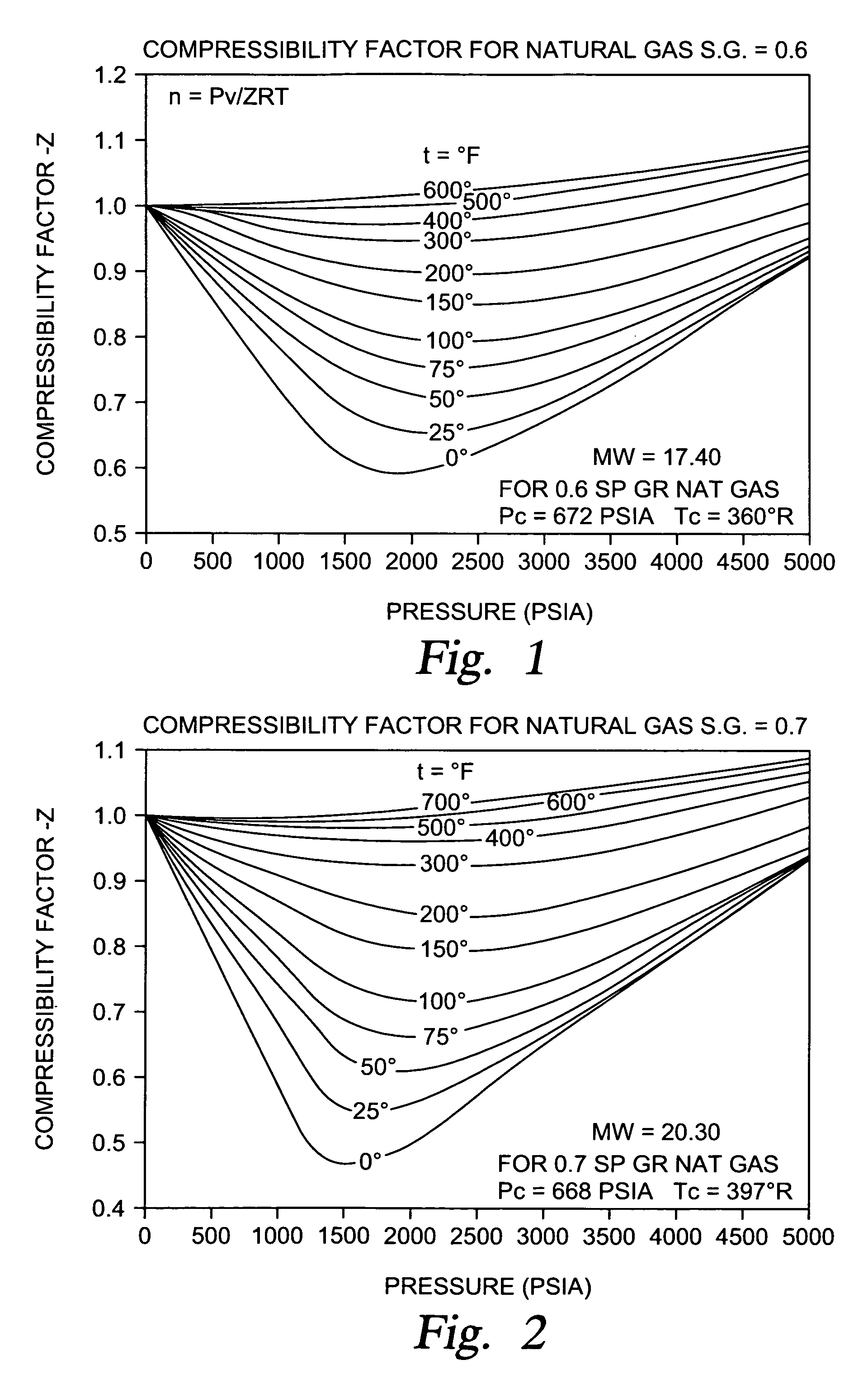
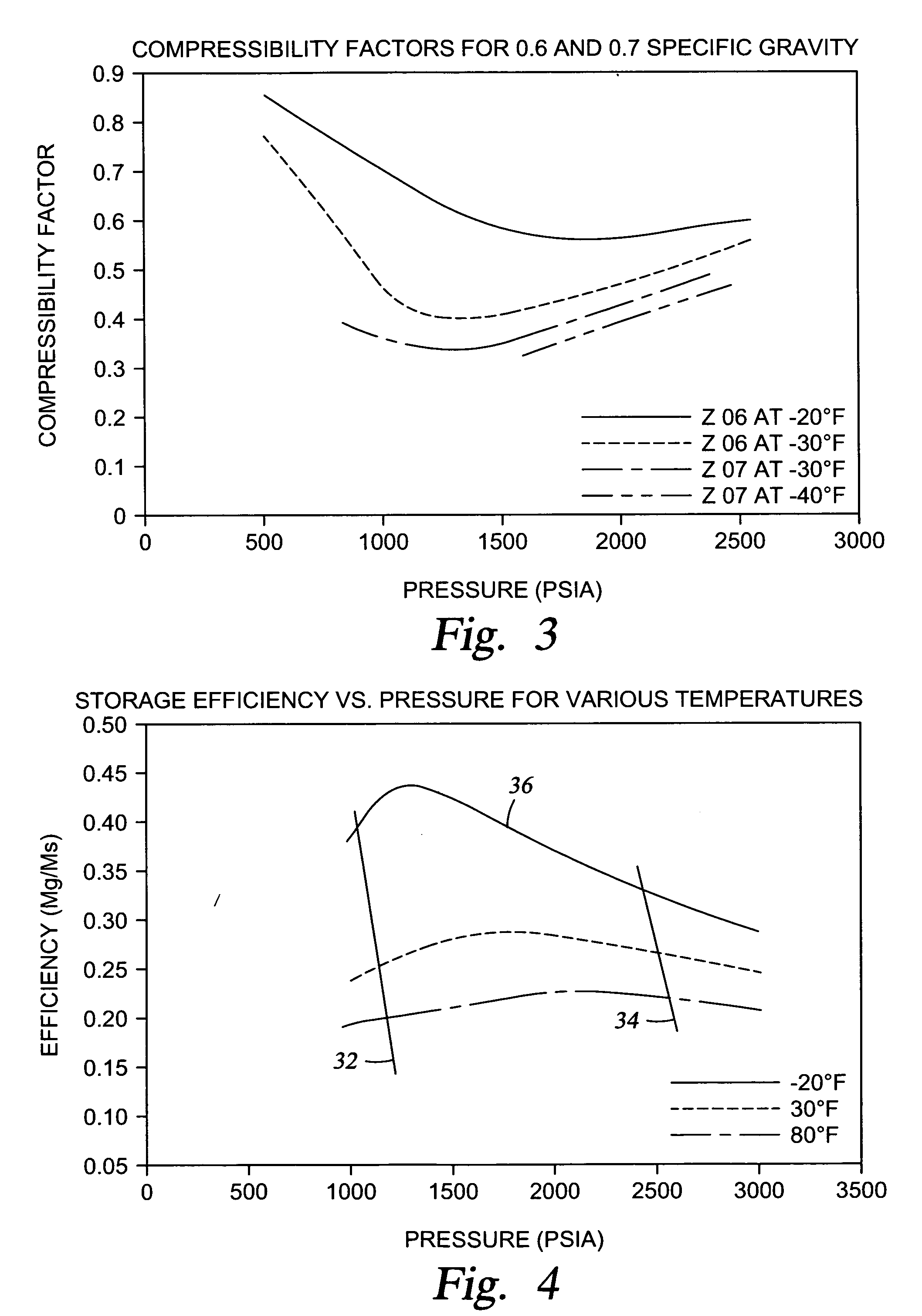
Examples
Embodiment Construction
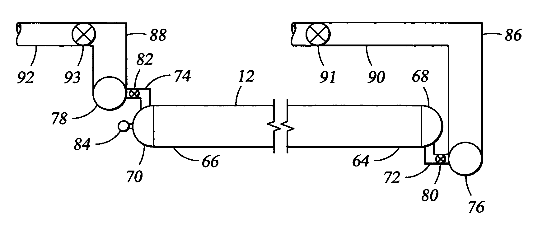
[0075] In the description which follows, like parts are marked throughout the specification and drawings with the same reference numerals, respectively. The drawing figures are not necessarily to scale. Certain features of the preferred embodiments may be shown in exaggerated scale or in somewhat schematic form and some details of conventional elements may not be shown in the interest of clarity and conciseness. It is understood that the systems disclosed in this application are intended to be designed in accordance with applicable design standards for the uses intended, as published by recognized regulatory agencies, such as the American Petroleum Institute (API), American Society of Mechanical Engineering (ASME), and the Department of Transportation.
[0076] The present invention is directed to several areas including but not limited to methods and apparatus for gas storage and transportation; methods of construction for the storage apparatus; methods and apparatus for on-loading a...
PUM
| Property | Measurement | Unit |
|---|---|---|
| Thickness | aaaaa | aaaaa |
| Diameter | aaaaa | aaaaa |
| Temperature | aaaaa | aaaaa |
Abstract
Description
Claims
Application Information