Battery pack and method of producing the same

a battery pack and battery technology, applied in the field of batteries, can solve the problems of shortening the operating time, and deteriorating the operation sensitivity, and achieve the effect of improving the operating time and high performan

Inactive Publication Date: 2006-02-07
PANASONIC CORP
View PDF11 Cites 34 Cited by
  • Summary
  • Abstract
  • Description
  • Claims
  • Application Information

AI Technical Summary

Benefits of technology

[0019]A battery pack in the present invention comprises a battery cell and a protection circuit unit for protecting the battery cell from the overcurrent or the high temperature. The protection circuit unit is an integrated body which contains a protection IC and a printed circuit board mounted with a surface-mount type PTC thermistor. In the present structure, a surface-mount type PTC thermistor used in the protection circuit unit contributes to a higher performance.
[0020]A method for manufacturing battery packs in accordance with the present invention comprises the steps of soldering a protection IC and a surface-mount type PTC thermistor on a printed circuit board, heat-treating the above soldered printed circuit board, connecting a connection lead to the respective positive electrode and negative electrode of battery cell, and electrically connecting the connection leads with the printed circuit board. In accordance with the present manufacturing method, the operating time can be improved by applying a heat treatment on a surface-mount type PTC thermistor soldered on printed circuit board.

Problems solved by technology

Suppose the battery cell 1 and the battery cell 4 are connected simply with a metal lead wire instead of the PTC thermistor 7 with leads, and there can be a possibility of short-circuit trouble arising in the power supply line of electronic apparatus.
Thus conventional battery packs have problems that there are fear of shortening operating time and deteriorating sensitivity in the operation.
Thus the conventional battery pack has a problem that leads to a shorter operating time.

Method used


Image

  • Battery pack and method of producing the same
  • Battery pack and method of producing the same
  • Battery pack and method of producing the same

Examples


embodiment 1

(Embodiment 1)

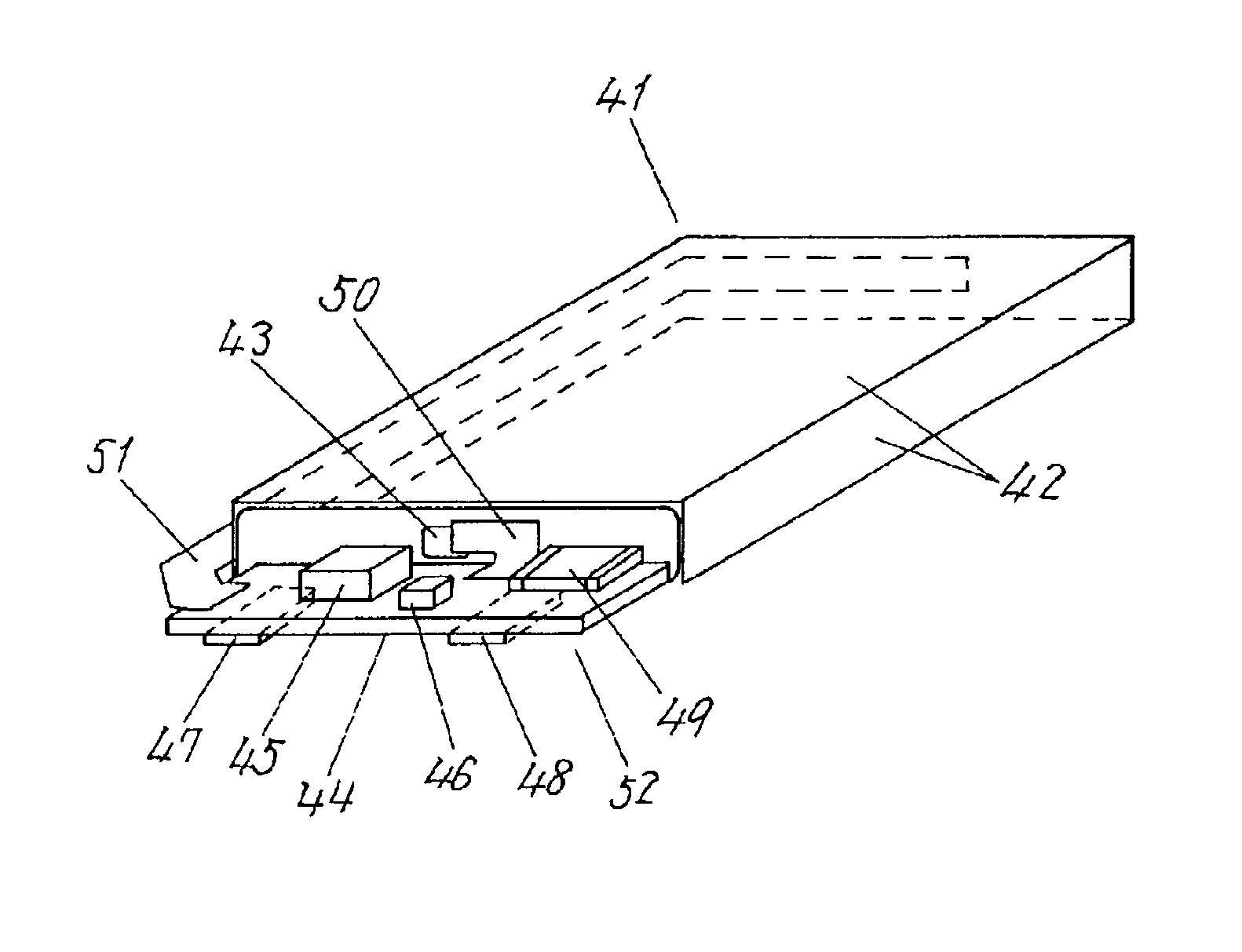
[0037]FIG. 1 is a perspective view of a battery pack in accordance with a first exemplary embodiment of the present invention. The battery pack comprises a prismatic battery cell 41 and a protection circuit unit 52. The protection circuit unit 52 comprises a printed circuit board 44 and a protection IC 45, a surface-mount type PTC thermistor 49 and an FET unit 46 which is formed basically of two FETs, mounted on a first mounting surface of the printed circuit board 44 using an SnAg system, or SnCu system, lead-free solder. The prismatic battery cell 41 is covered with a metal case, which case works also as the positive terminal 42, and the negative terminal 43 is disposed on only one surface among the surfaces of the prismatic battery cell 41. The printed circuit board 44 is provided on a second mounting surface, which is a surface opposite to the surface where the protection IC 45 is mounted, with the positive terminal 47 and the negative terminal 48 for leading respe...

embodiment 2

(Embodiment 2)

[0050]A battery pack in accordance with a second exemplary embodiment of the present invention, and the manufacturing method are described referring to the drawings.

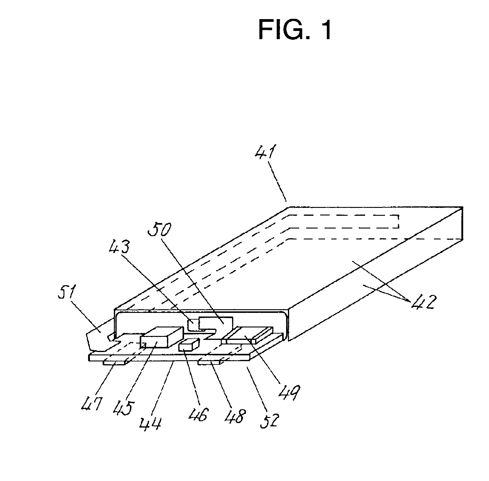
[0051]FIG. 2 is a perspective view of a battery pack in accordance with a second exemplary embodiment of the present invention. The battery pack comprises a prismatic battery cell 61 and a protection circuit unit 73. The protection circuit unit 73 comprises a printed circuit board 64 and a protection IC, a surface-mount type PTC thermistor 69 and an FET unit 66 which is formed basically of two FETs, mounted on the first surface of printed circuit board 64, and soldered thereon using an SnAg alloy, or SnCu alloy, lead-free solder. The prismatic battery cell 61 is covered with a metal case, which works also as the positive terminal 62, and the negative terminal 63 is disposed on only one surface among the surfaces of the prismatic battery cell 61. The printed circuit board 64 is provided on a second mounting ...

embodiment 3

(Embodiment 3)

[0060]A battery pack in accordance with a third exemplary embodiment of the present invention, and the manufacturing method are described referring to the drawings.

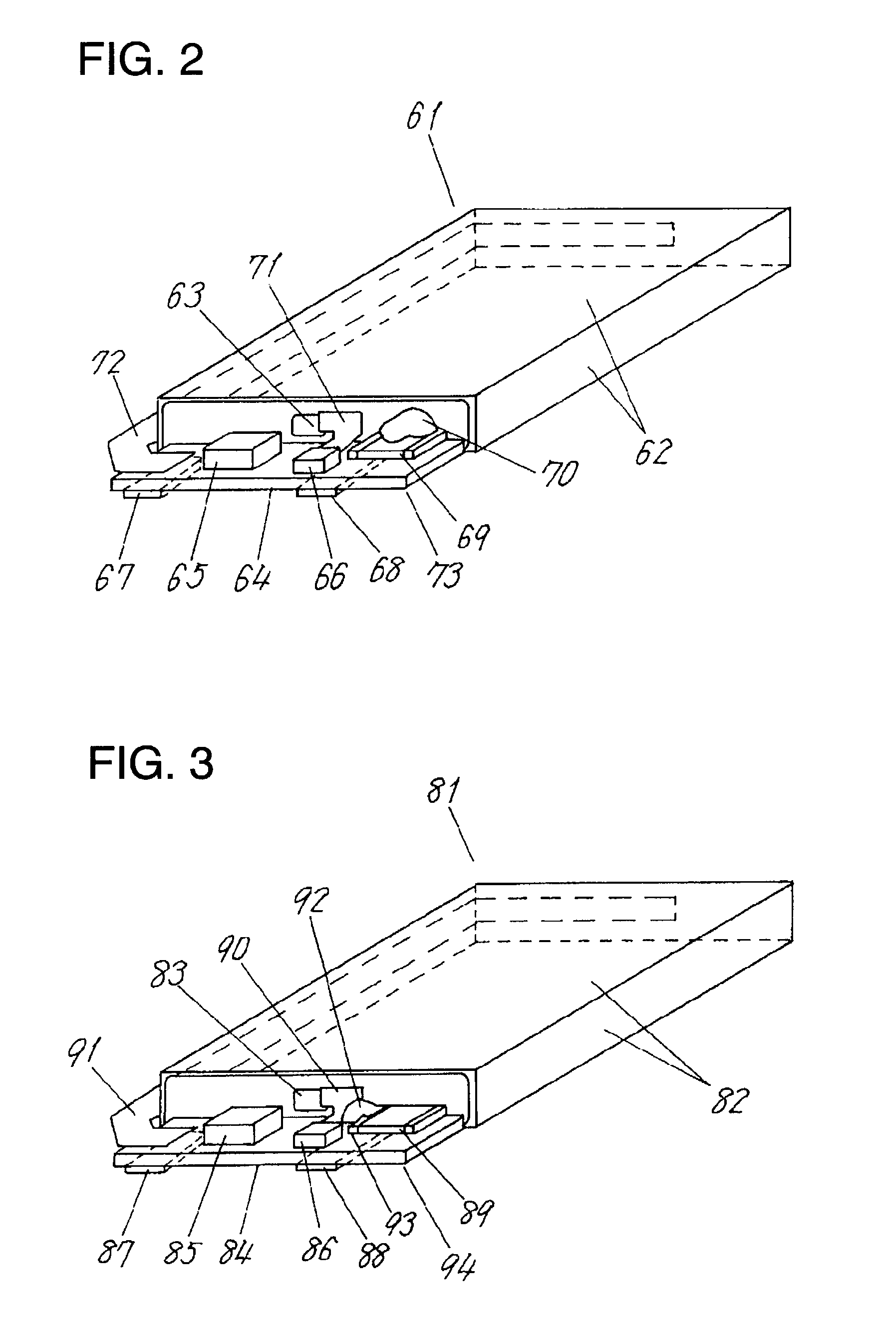
[0061]FIG. 3 is a perspective view of a battery pack in accordance with a third exemplary embodiment of the present invention. The battery pack comprises a prismatic battery cell 81 and a protection circuit unit 94. The protection circuit unit 94 comprises a printed circuit board 84 and a protection IC, a surface-mount type PTC thermistor and an FET unit 86 which is formed basically of two FETs, mounted on the first surface of printed circuit board 84, and soldered thereon using an SnAg alloy, or SnCu alloy, lead-free solder. The prismatic battery cell 81 is covered with a metal case, which works also as the positive terminal 82, and the negative terminal 83 is disposed on only one surface among the surfaces of the prismatic battery cell. The printed circuit board 84 is provided on a second mounting surface,...


PUM

PropertyMeasurementUnit
melting pointaaaaaaaaaa
resistanceaaaaaaaaaa

Abstract

The protection circuit unit 52 is an integrated body comprising a surface-mount type PTC thermistor 49 mounted by a soldering on a printed circuit board 44 through reflow soldering or the like soldering method together with a protection IC 45 and a FET unit 46. The surface-mount type PTC thermistor 49, as compared with a PTC thermistor with leads, can be mounted readily on the printed circuit board 44, without requiring bending and welding work of a lead to be connected to a negative terminal of prismatic battery cell 41, for forming a circuit. As a result, change in a resistance due to a bending stress, a thermal stress, etc. can be eliminated. Furthermore, a degree of thermal coupling with the battery cell 41 can be adjusted by changing a location of the thermistor 49. Thus, varieties of control functions can be implemented.

Description

TECHNICAL FIELD[0001]The present invention relates to a battery pack having a function for protecting the battery pack from overcurrent or over heat, and the method for manufacturing the battery pack.BACKGROUND ART[0002]A conventional battery pack disclosed in the Japanese Laid-open Patent No. H7-57721 is described with reference to drawings.[0003]FIG. 10A is a cross sectional view, as viewed from the top, of a conventional battery pack with key part, where part of the case have been cut off. FIG. 10B is a cross sectional front view with key part, where part of the case have been cut off.[0004]Referring to FIG. 10A and FIG. 10B, a battery pack 12 comprises a first battery cell 1, a second battery cell 4, and a thermistor 7 with leads, which have been packed in a case 9. The first battery cell 1 has a protruding positive terminal 2 and a negative terminal 3 provided at the opposite surface. The second battery cell 4 likewise has a protruding positive terminal 5 and a negative termina...

Claims


Application Information

Patent Timeline
Patent Type & Authority Patents(United States)
IPC IPC(8): H01M10/50H01C1/14H01M2/10H01M6/50H01M10/42H01M10/60H01M10/613H01M10/637H01M10/647H01M10/653H01M10/6553H01M10/6554H05K1/02H05K1/18
CPCH01C1/14H01C1/1406H01M2/1016H01M10/42Y10T29/49114H01M2200/10H05K1/0201H05K1/181Y10T29/49108H01M2200/00Y02E60/10H01M50/20
Inventor IKEUCHI, KIYOSHIKOYAMA, YASUKAZU
Owner PANASONIC CORP
Why Eureka
Try Eureka