

Head positioning system, disk drive apparatus using the same, and head positioning method
a positioning system and disk drive technology, applied in the direction of electric programme control, instruments, program control, etc., can solve the problems of affecting the operation of the disk drive apparatus, the control of the positioning head supporting mechanism may not be precisely performed, and the bearing size is accordingly decreased, so as to reduce the size of the disk drive apparatus, the effect of promoting the influence of static friction and increasing the price of the apparatus
- Summary
- Abstract
- Description
- Claims
- Application Information
AI Technical Summary
Benefits of technology
Problems solved by technology
Method used
Image

Examples
embodiment 1
[0077](Embodiment 1)
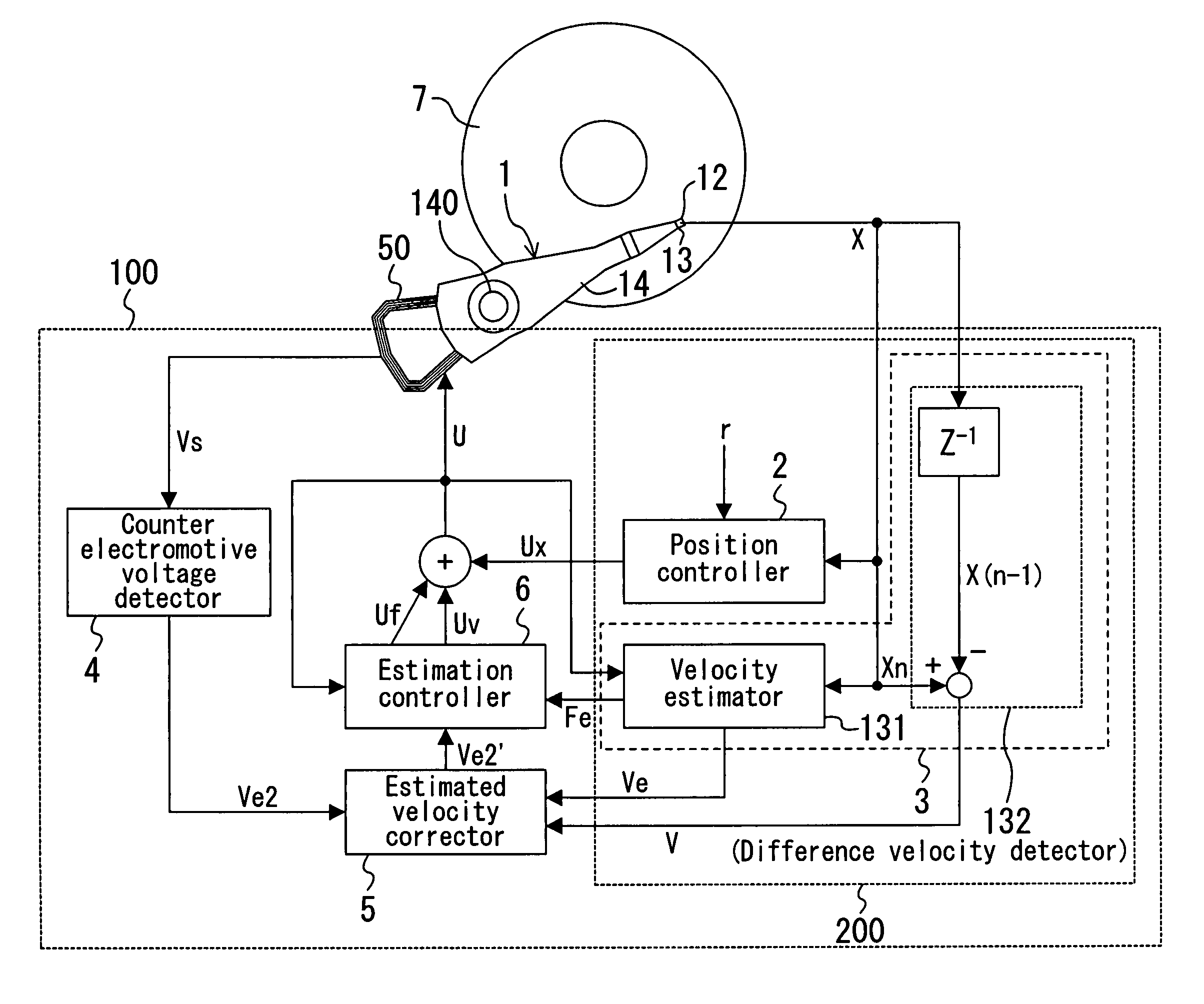
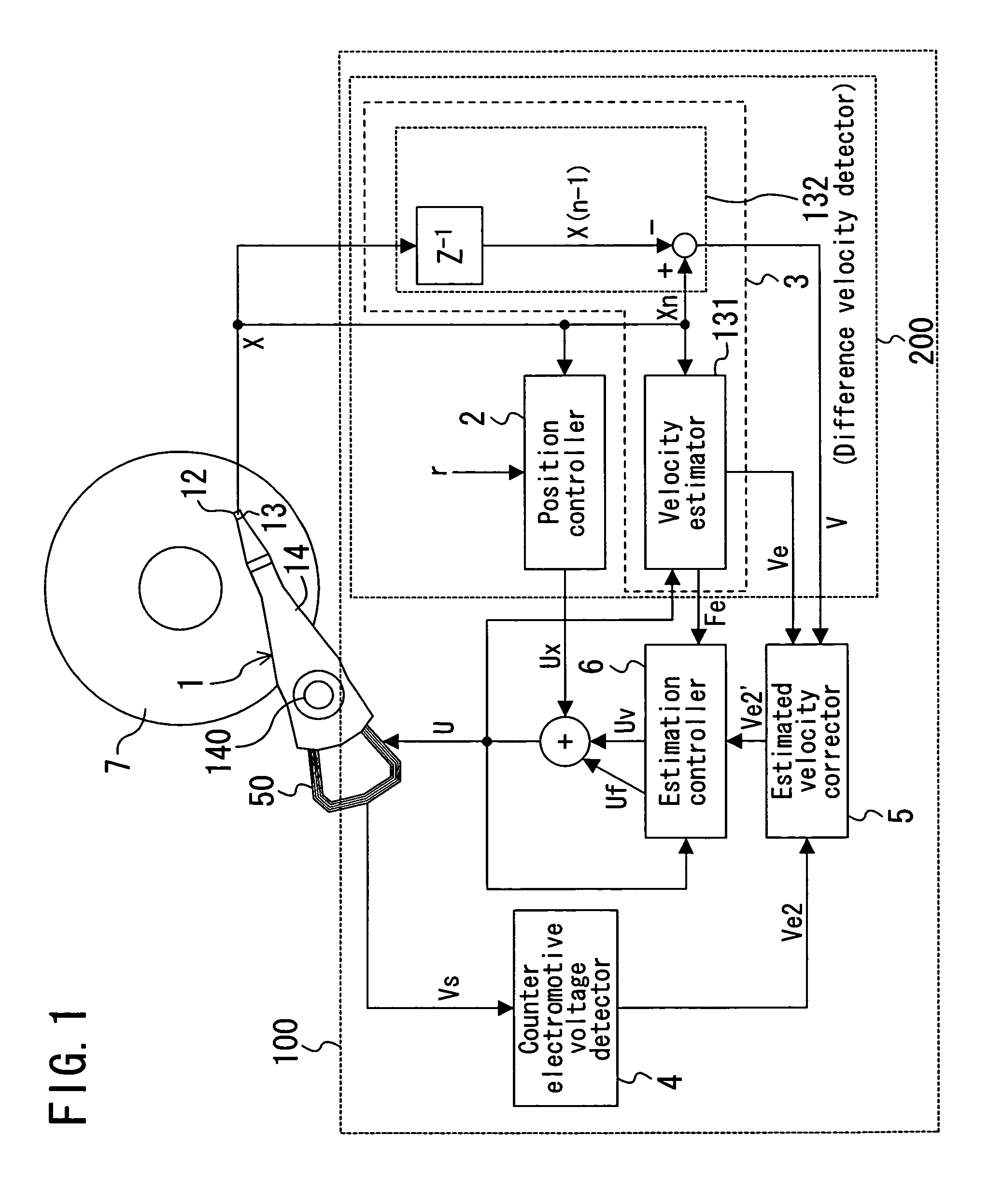
[0078]FIG. 1 is a block diagram showing the structure of a head positioning system according to embodiment 1 of the present invention.
[0079]In FIG. 1, a magnetic disk (disk-shaped information recording medium) 7, hereinafter simply referred to as “disk”, is supported at its center that corresponds to the center of rotation, and rotated by a rotation control mechanism, such as a spindle motor, for example. A magnetic head 12 (hereinafter, “head 12”) for writing / reading information on / from the disk 7 is integrally formed at the tip of a head slider 13. The head slider 13 is mounted at an end of a head supporting mechanism 14. The head supporting mechanism 14 is driven by an actuator 50 around a rotation shaft 140 to move the head 12. The actuator 50 has a voice coil motor (VCM) as driving means and moves the head 12 provided at the tip of the head supporting mechanism 14 using the voice coil motor. The head slider 13, the head supporting mechanism 14 and the actuat...
embodiment 2
[0122](Embodiment 2)
[0123]FIG. 13 is a block diagram showing the structure of a head positioning system according to embodiment 2 of the present invention.
[0124]In FIG. 13, the structure of the mechanism of a control section 102 is the same as that of embodiment 1, and therefore, description thereof is herein omitted. In FIG. 13 of embodiment 2, like elements are denoted by like reference numerals used in embodiment 1.
[0125]However, a basic control section 202 included in the control section 102 is different from the basic control section 200 of embodiment 1 in that it is not necessary to provide the velocity detector 3 in the basic control section 202. The detected head position signal x is directly input to the estimated velocity corrector 5. Furthermore, embodiment 2 is difference from embodiment 1 in that the estimated head velocity signal Ve2 and an estimated head transfer position signal xe2 obtained by integrating the estimated head velocity signal Ve2 are generated in the co...
embodiment 3
[0127](Embodiment 3)
[0128]FIG. 14 is a block diagram showing the structure of a head positioning system according to embodiment 3 of the present invention.
[0129]In FIG. 14, the structure of the mechanism of the control section 103 is the same as those of embodiments 1 and 2, and therefore, description thereof is herein omitted. Further, like elements are denoted by like reference numerals used in FIG. 1 of embodiment 1.
[0130]Embodiment 2 is different from embodiment 1 in that, in the control section 103, the estimation controller 6 receives only the corrected estimated velocity signal Ve2′, and the control amount signal U is not fed back to the estimation controller 6. The estimation controller 6 multiplies the corrected estimated velocity signal Ve2′ by the velocity feedback gain Kv to output the velocity control signal Uv.
[0131]A position controller 2 included in a basic control section 203 multiplies the position error signal e, which is a difference between the detected head pos...
PUM
 Abstract
Description
Claims
Application Information