Discretization processing method of transfer function in continuous time systems, system and program therefor, and compensator and feedback control system using the same

a technology of continuous time system and discrete system, which is applied in the direction of ignition automatic control, electric controllers, instruments, etc., can solve the problems of inability to transform, deviating characteristics in the high frequency region of the transformed discrete system, and inability to maintain amplitude characteristics in analog continuous time systems. , to achieve the effect of reducing processor load, reproducing accurately, and reducing product manufacturing costs

Inactive Publication Date: 2006-02-07
FUJITSU LTD
View PDF6 Cites 4 Cited by
  • Summary
  • Abstract
  • Description
  • Claims
  • Application Information

AI Technical Summary

Benefits of technology

[0033]Still further, according to the present invention, preferably the calculation step of the new transfer function in continuous time systems includes the step of approximating to a transfer function from the shifted frequency response data by means of the least square method. This produces the approximation easier.
[0034]Accordingly, particularly when performing digital control by discretizing a compensator in the feedback control systems, it is no more necessary to employ a method of substituting an analog control circuit to cope with poles and zero points near the Nyquist frequency, nor to use a high speed processor to increase the sampling frequency. Thus the product manufacturing cost can be reduced.
[0035]In addition, when it is difficult to coincide the approximation, the original characteristics can be reproduced accurately by increasing the number of degrees at the time of approximation. On the other hand, by reducing the number of degrees at the time of approximation, it becomes possible to reduce the processor load.

Problems solved by technology

When this folding is made, as shown in FIG. 22, an overlap distortion (or an alias distortion) is produced by the occurrence of the overlap in the amplitude characteristic, causing that the amplitude characteristic in analog continuous time systems cannot be maintained.
On the other hand, when poles and zero points are located near the Nyquist frequency or higher than the Nyquist frequency, it is often occurred that the characteristics in the high frequency region of the transformed discrete systems deviate greatly from the characteristics in continuous time systems, which causes a problem of such a method.
Hei-5-210419, etc.) However, according to this method, it is not possible to transform when the poles and zero points of the transfer function in continuous system are located at higher frequency than the Nyquist frequency because tan θ in the above formula (1) becomes greater than π / 2, which produces a negative frequency value after the shift.
Therefore this frequency shift method cannot be employed and it is still difficult to make the characteristics coincident.
Accordingly, there has been a problem in the prior art that only an inaccurate transfer function having different characteristics is obtained when a transfer function being designed and identified in continuous time systems is intended to discretize to perform digital processing.
However, there is a problem that characteristics of analog circuits vary, in contrast to digital circuits, because of production dispersion or aged deterioration in electronic components.
Also, analog circuits become costly when it is intended to use in mass-produced control units.
This becomes also costly and disadvantageous considering the use of such processors for mass-produced control units.

Method used


Image

  • Discretization processing method of transfer function in continuous time systems, system and program therefor, and compensator and feedback control system using the same
  • Discretization processing method of transfer function in continuous time systems, system and program therefor, and compensator and feedback control system using the same
  • Discretization processing method of transfer function in continuous time systems, system and program therefor, and compensator and feedback control system using the same

Examples


first embodiment

[First Embodiment]

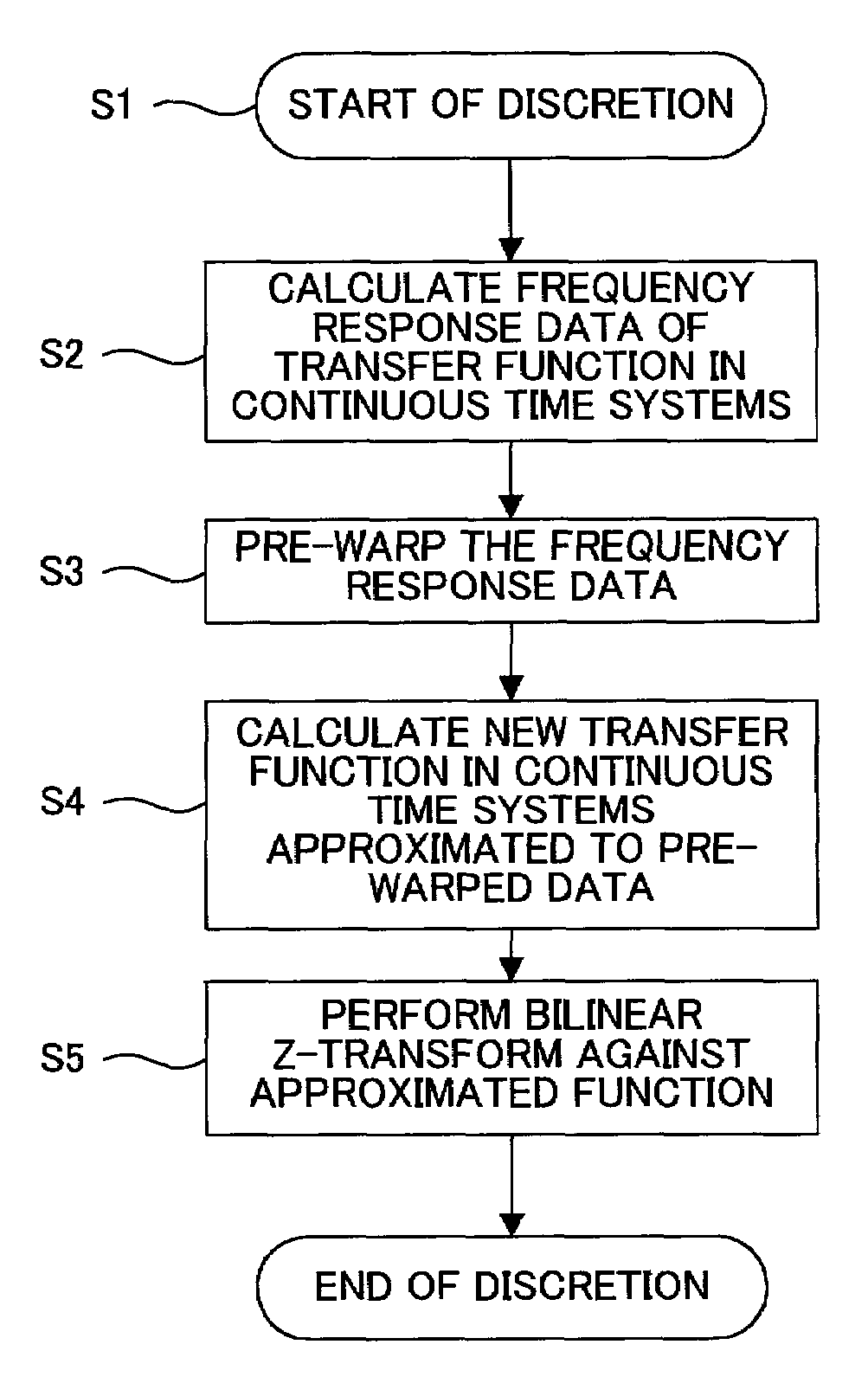
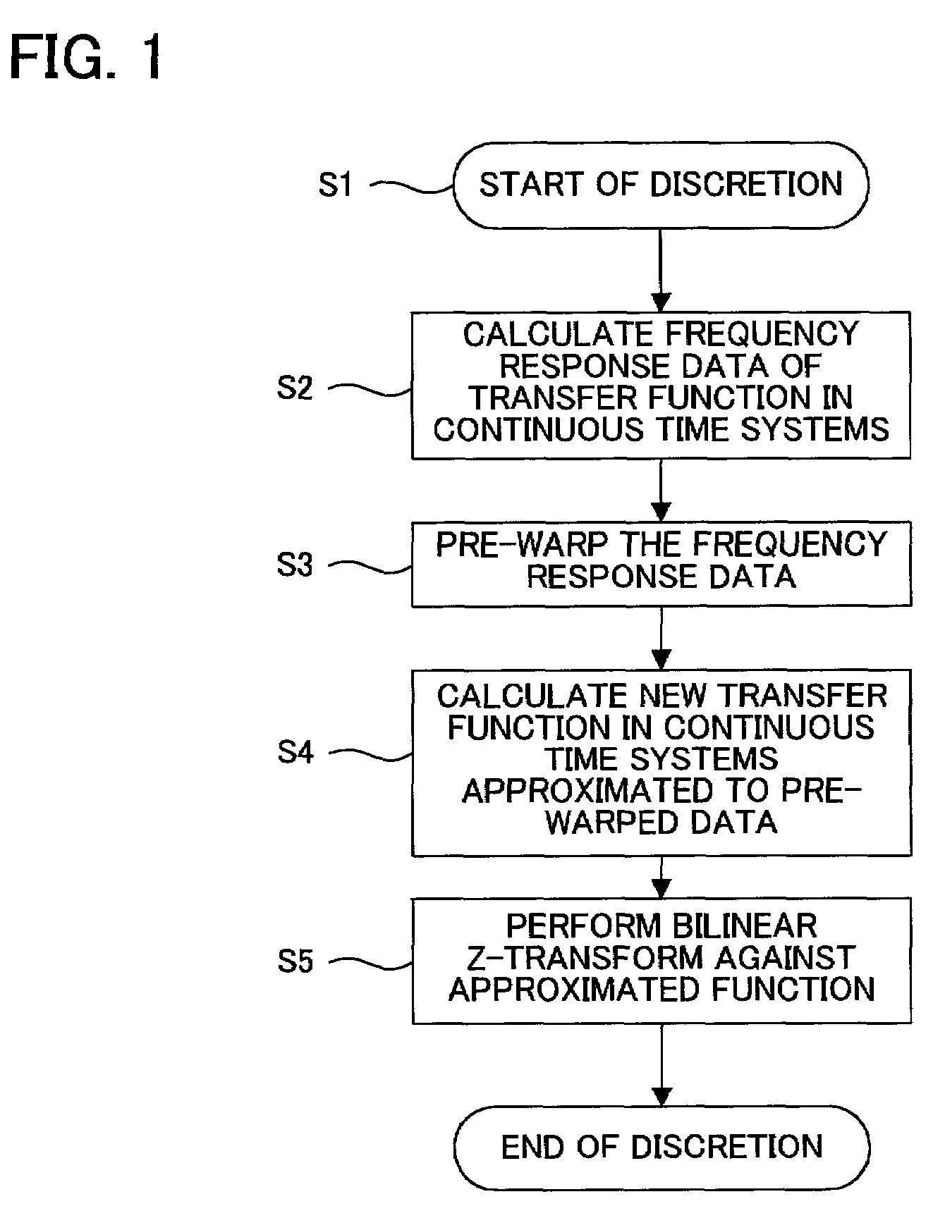
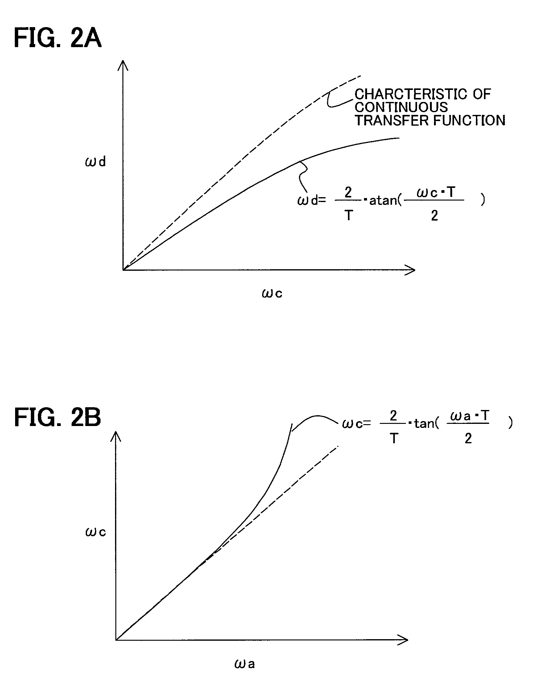
[0063]FIG. 1 shows a flowchart of the discretization processing according to a first embodiment of the present invention. FIGS. 2A and 2B show explanation diagrams of the principle of the discretization processing according to the present invention. FIG. 3 shows a block diagram of the discretization processing according to the method shown in FIG. 1. FIG. 4 shows an explanation diagram of a pre-warp processing shown in FIG. 1. FIGS. 5A, 5B and 5C show explanation diagrams of poles and zero points in the embodiment shown in FIG. 1. FIG. 6 shows an explanation diagram of the generation operation of a pre-warping and approximation function in the embodiment shown in FIGS. 5A to 5C. Further, FIG. 7 shows frequency characteristic diagrams of a transfer function in continuous time systems before transformation and a transfer function in discrete time systems after transformation according to the embodiment shown in FIG. 5.

[0064]First, referring to FIGS. 5A to 5C and 6, a...

second embodiment

[Second Embodiment]

[0081]FIG. 8 shows a flowchart of the discretization processing according to a second embodiment of the present invention. FIG. 9 shows an explanation diagram of poles and zero points as a result of the discretization processing. FIG. 10 shows a characteristic diagram of an approximated transfer function in continuous time systems according to the second embodiment of the present invention shown in FIG. 8. Also, FIG. 11 shows a frequency characteristic diagram as a result of the discretization processing according to the second embodiment of the present invention shown in FIG. 8.

[0082]In this embodiment, the approximation on the five (5) orders is introduced at the time of approximation by the least square method in step S4, which is two orders higher than the transfer function in continuous time systems, instead of the approximation on the same order as that in the first embodiment. More specifically, while steps S11, 12, 13 and 15 are identical to steps S1, 2, 3...

third embodiment

[Third Embodiment]

[0086]FIG. 12 shows a flowchart of the discretization processing according to a third embodiment of the present invention. FIG. 13 shows an explanation diagram of poles and zero points as a result of the discretization. FIG. 14 shows a frequency characteristic diagram of the approximated transfer function in continuous time systems according to the third embodiment shown in FIG. 12. Also, FIG. 15 shows a frequency characteristic diagram as a result of the discretization according to the third embodiment shown in FIG. 12.

[0087]In this third embodiment, as compared to the first embodiment, the approximation is carried out on first order, which is one order lower than in the first embodiment, when approximating by the least square method in step S4, instead of approximating on the same order as the transfer function in continuous time systems. More specifically, in FIG. 12, steps S21, 22, 23 and 25 are identical to steps S1, 2, 3 and 5 shown in FIG. 1. However, step S...


PUM

PropertyMeasurementUnit
Nyquist frequencyaaaaaaaaaa
frequencyaaaaaaaaaa
Nyquist frequencyaaaaaaaaaa

Abstract

A discretization processing method for transforming a transfer function in continuous time systems to a transfer function in discrete time systems is disclosed. To obtain the new transfer function, angular frequency ωa of the original transfer function in continuous time systems is transformed to angular frequency ωc using the bilinear z-transform of the inverse characteristic. In the discretion processing result, the equivalent characteristics of the original transfer function in continuous time systems can be obtained by performing the bilinear z-transform against the new transfer function in continuous time systems having been obtained by the angular frequency transformation of inverse characteristic.

Description

BACKGROUND OF THE INVENTION[0001]1. Field of the Invention[0002]The present invention relates to a discretization processing method for transforming a transfer function in continuous time systems to a transfer function in discrete time systems, a system and a program therefor, and a compensator and a feedback control system using the same. More particularly, the present invention relates to a discretization processing method appropriate for discretizing a transfer function in continuous time systems in which poles and zero points of the transfer function in continuous time systems locate at a frequency near the Nyquist frequency or higher than the Nyquist frequency, a system and a program therefor, and a compensator and a feedback control system using the same.BACKGROUND OF THE INVENTION[0003]As digital equipment becomes popularly used in recent years, analog signal processing is being substituted by digital signal processing. The analog signal processing is performed in continuous ...

Claims


Application Information

Patent Timeline
Patent Type & Authority Patents(United States)
IPC IPC(8): G06F17/10G05B13/02G11B21/10G05B21/02G05B23/02G11B7/09G11B11/105
CPCG05B21/02G11B11/10576G11B7/0901
Inventor IKAI, YOSHIAKI
Owner FUJITSU LTD
Why Eureka
Try Eureka