Temperature sensor

a technology of temperature sensor and core wire, which is applied in the field of temperature sensor, can solve the problems of troublesome handling of temperature sensor, inability to ignore the resistance of lead wire due to the difference in length, and the disadvantage of the related art, so as to achieve the effect of reducing the contact resistance at the connecting portion between the lead wire and the core wire or the connector, avoiding the loss of data, and ensuring the accuracy of high temperature detection

Inactive Publication Date: 2006-02-14
NGK SPARK PLUG CO LTD
View PDF44 Cites 11 Cited by
  • Summary
  • Abstract
  • Description
  • Claims
  • Application Information

AI Technical Summary

Benefits of technology

[0007]The invention has been conceived in view of the background of the aforementioned related art, and has an object to provide a temperature sensor, which can detect the temperature in an excellent precision without any correction according to the length of the lead wires and which can exhibit an excellent durability.
[0010]In the temperature sensor of the invention, each of the lead wires is made of the mixed twisted wire including the first electric wires and the second electric wires. The first electric wires are made of the first conductor containing copper so that the difference in the resistance due to the difference between the lengths of the lead wires is remarkably small. Even without any correction of the temperature characteristics of the temperature sensor according to the length of the lead wires, the error of the temperature detected raises no problem in the precision. On the other hand, the second electric wires are made of the second conductor having a higher bending resistance and a higher tensile strength than those of the first conductor, so that they can be prevented from being disconnected by the use of a long period thereby to exhibit an excellent durability.
[0011]According to the temperature sensor of the invention, therefore, it is possible to detect the temperature in an excellent precision without any correction according to the length of the lead wires and to exhibit an excellent durability.
[0013]In the temperature sensor of the invention, it is preferred that each of the lead wires has the first electric wires enclosing the second electric wires. Usually, the individual lead wires are caulked at their one-end sides to the paired core wires and are connected through the individual core wires with the thermo-sensitive element. On the other hand, the other-end sides of the individual lead wires are caulked and connected with the connector. If the second electric wires are enclosed by the first electric wires made of the first conductor containing properly soft copper, therefore, the individual lead wires are satisfactorily caulked and are properly connected with the core wires and the connector. As a result, the contact resistance at the connecting portions between the lead wires and the core wires or the connector can be reduced to exhibit the excellent durability.
[0014]A thermistor, a metallic resister or the like can be adopted as the thermo-sensitive element. The temperature sensor of the invention has prominent effects in case an element having a low minimum resistance within a measurement temperature range is used as the thermo-sensitive element. Specifically, the effects are prominent in case the thermo-sensitive element is exemplified by a thermistor having a minimum resistance not higher than 100 Ω within a measurement temperature range (of 100 to 900° C., for example) or a platinum resistance element having a minimum resistance not higher than 200 Ω within a measurement-temperature range (of −40 to 900° C., for example) In case the thermo-sensitive element is the thermistor element, excellent effects are obtained in case the thermistor element used has a low B constant (not larger than 3,000 K, for example) In case the minimum resistance within the measurement temperature range of the thermo-sensitive element is thus low, it may occur that the difference in the resistance due to the difference between the lengths of the lead wires cannot be ignored. In the temperature sensor of the invention, on the contrary, the difference in the resistance due to the difference between the lengths of the lead wires is so small that the temperature sensor can exhibit a high temperature detecting precision reliably.

Problems solved by technology

However, the aforementioned temperature sensors of the related art have a disadvantage when they are mounted in the vehicle, because the individual lead wires are made of the SUS wires or copper wires.
Even if the temperature characteristics of the temperature sensor or the variation of the electric signal to the change in the temperature should be corrected according to the lengths of the lead wires by means of a hardware or software, moreover, the individual adjustments or changes according to the lengths of the lead wires are necessary so that the temperature sensor is troublesome in handling.
Therefore, the change in the electric signal for the temperature of 1° C. becomes lower than that of the related art, and the difference between the resistances of the lead wires due to the difference in the length cannot be ignored to make the handling inconveniences notable.
However, the copper wires have a low bending resistance and a low tensile strength.
Therefore, the temperature sensor having the lead wires made of the copper wires may be disconnected by the use of a long period and may be feared in its durability.

Method used


Image

  • Temperature sensor
  • Temperature sensor
  • Temperature sensor

Examples


Embodiment Construction

[0023]An embodiment of the invention will be described with reference to the accompanying drawings.

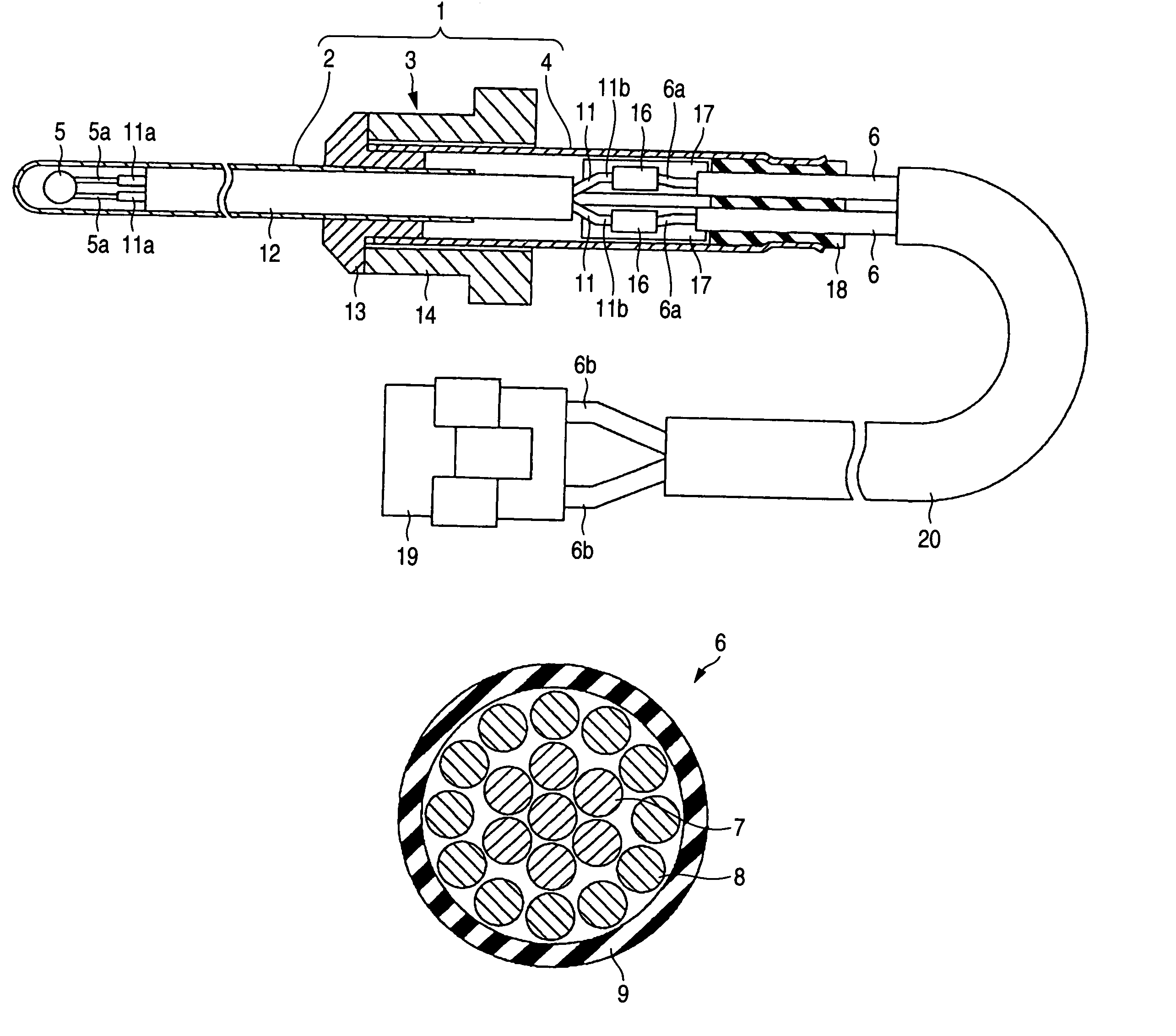
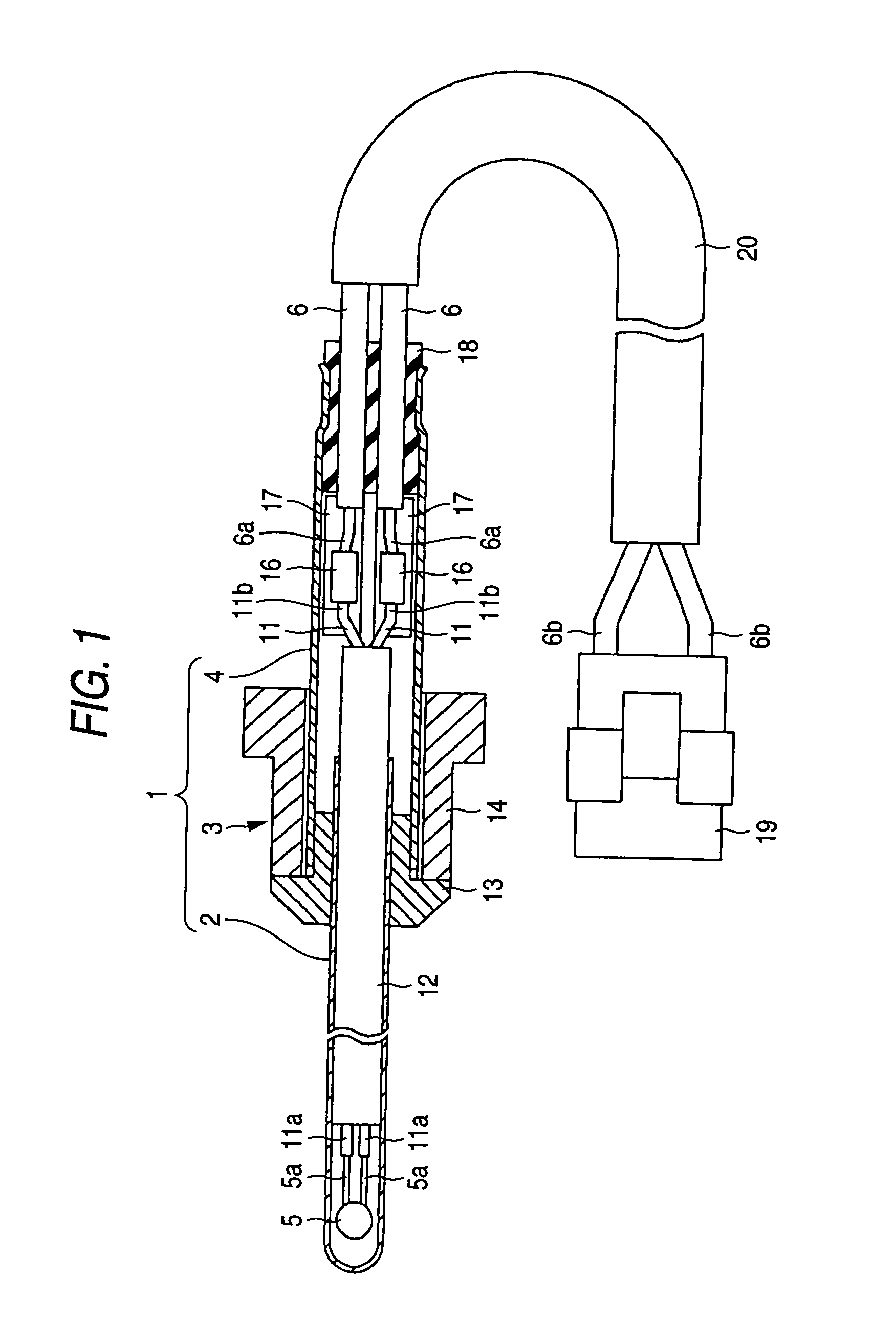
[0024]FIG. 1 shows a sectional view of a temperature sensor of the embodiment. This temperature sensor is mounted in the exhaust passage of a not-shown vehicle and is used for detecting the temperature of the exhaust gas over a wide range. This temperature sensor is provided with: a housing 1; a thermistor housed in the housing 1 for acting as a thermo-sensitive element to output the electric characteristics varying with the temperature, as an electric signal; and a pair of lead wires 6 for extracting the electric signal from the thermistor 5 to the outside of the housing 1.

[0025]More specifically, the housing 1 is constructed of a first housing 2, a nut portion 3 and a second housing 4. The first housing 2 is formed into a cylindrical shape having a closed leading end. On the leading end side of this first housing 2, there is arranged the thermistor 5 for outputting a resistance varyi...


PUM

PropertyMeasurementUnit
lengthaaaaaaaaaa
lengthaaaaaaaaaa
lengthsaaaaaaaaaa

Abstract

A temperature sensor comprising: a housing; a thermo-sensitive element housed in the housing for outputting electric characteristics varying with a temperature, as an electric signal; and a pair of lead wires connected at their one-side ends with the thermo-sensitive element for extracting the electric signal from the thermo-sensitive element to an outside of the housing, wherein at least one of the lead wires is made of a mixed twisted wire including: first electric wires made of a first conductor containing copper; and second electric wires made of a second conductor having a higher bending resistance and a tensile strength than those of the first conductor.

Description

FIELD OF THE INVENTION[0001]The present invention relates to a temperature sensor. This temperature sensor of the invention is suitably used in the case for detecting the temperature of the exhaust gas or the like of a vehicle.BACKGROUND OF THE INVENTION[0002]The temperature sensors of JP-A-2001-56256 and JP-A-5-264368 are known in the related art. These temperature sensors are individually provided with: a housing; a thermo-sensitive element housed in the housing for outputting electric characteristics varying with the temperature, as an electric signal; and a pair of lead wires connected at their one-side ends through a pair of core wires with the thermo-sensitive element for extracting the electric signal from the thermo-sensitive element to the outside of the housing. The temperature sensor of JP-A-2001-56256 uses SUS wires (or stainless steel wires) as those lead wires, and the temperature sensor of JP-A-5-264368 uses copper wires (or nickel-plated annealed copper wires).[0003]...

Claims


Application Information

Patent Timeline
Patent Type & Authority Patents(United States)
IPC IPC(8): B21F7/00G01K7/16G01K7/22G01K13/02
CPCG01K13/02G01K2205/04
Inventor HANZAWA, GONISHI, MASAHIKOIWAYA, MASAKICHOSOKABE, TAKAAKI
Owner NGK SPARK PLUG CO LTD
Why Eureka
Try Eureka