Stage device, exposure system, method of device manufacture, and device

a technology of exposure apparatus and stage device, which is applied in the direction of microlithography exposure apparatus, printers, instruments, etc., can solve the problems of vibration of the first transmitting member, and achieve the effects of effective suppression, effective prevention of reaction force, and improved exposure accuracy

Inactive Publication Date: 2006-02-14
NIKON CORP
View PDF8 Cites 25 Cited by
  • Summary
  • Abstract
  • Description
  • Claims
  • Application Information

AI Technical Summary

Benefits of technology

[0041]The second exposure apparatus of the present invention further can comprise a projection optical system that projects the pattern onto the substrate and a second supporting frame that is provided independently of the first supporting frame with respect to a vibration and supports the projection optical system. In the second exposure apparatus of the present invention, as mentioned above, the counter stage moves in the direction opposite to the stage in accordance with the movement of the stage and the reaction force is absorbed. The damping member damps a reaction force that cannot be absorbed and a vibration of the first supporting frame due thereto. Hence, it is possible to effectively prevent the reaction force accompanied by the driving of the stage from becoming a vibration factor of the projection optical system supported by the second supporting frame different from the first supporting frame. The first supporting frame and the second supporting frame have an independent relationship in respect to the vibration, so that there is little danger that, if a slight vibration remai

Problems solved by technology

In such a case, the mover is relatively driven to the stator together with the sample stage and a reaction fo

Method used


Image

  • Stage device, exposure system, method of device manufacture, and device
  • Stage device, exposure system, method of device manufacture, and device
  • Stage device, exposure system, method of device manufacture, and device

Examples


first embodiment

[0056]The first embodiment of the present invention will be described below with reference to FIGS. 1 to 5.

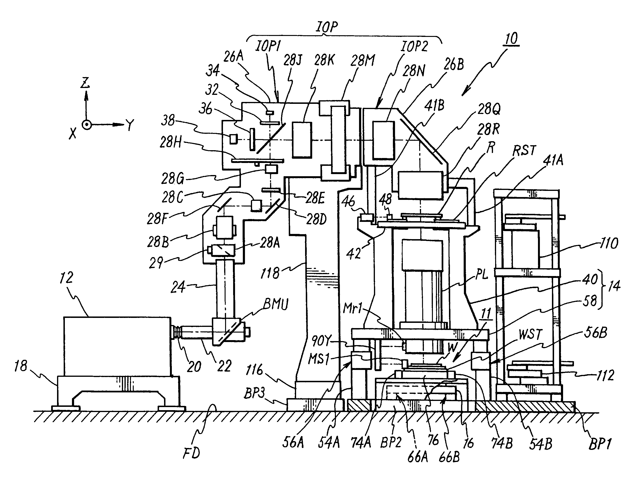
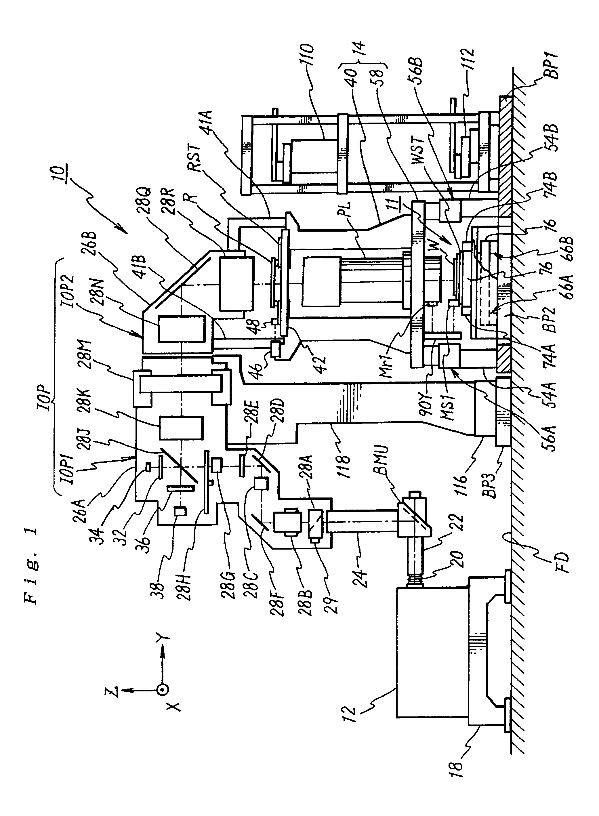
[0057]FIG. 1 schematically shows the overall constitution of an exposure apparatus 10 according to the first embodiment. The exposure apparatus 10 is a scanning exposure apparatus based on the step-and-scan method, that is a so-called scanning stepper, which synchronously moves a reticle R as a mask and a wafer W as a base (and a sample) in a one-dimensional direction (in this case, the Y-axis direction) and transfers circuit patterns formed on the reticle R onto each shot area on the wafer W via a projection optical system PL.

[0058]The exposure apparatus 10 comprises: a light source 12; an illumination optical system IOP which illuminates the reticle R with illumination light from the light source 12; a reticle stage RST serving as a mask stage which holds the reticle R; the projection optical system PL which projects illumination light (ultraviolet pulse light) emitted from t...

second embodiment

[0154]Next a description is given of the second embodiment of the present invention with reference to FIGS. 6 to 8. Herein, the same reference numerals denote the same or equivalent to components of the above first embodiment, and the description is brief or is omitted.

[0155]FIG. 6 schematically shows the constitution of the main portion of an exposure apparatus 100 according to the second embodiment. In a manner alike to the exposure apparatus 10 according to the first embodiment, the exposure apparatus 100 is a reduction projection exposure apparatus based on the step-and-scan method, that is, a so-called scanning stepper, which transfers the pattern of the reticle R as a mask onto the wafer W as a substrate.

[0156]In the exposure apparatus 100, the constitutions of the reticle stage RST and the driving mechanism, etc. and the constitution of the main column 14 as a holding portion differ much from those in the aforementioned exposure apparatus 10. Therefore, the different points w...

third embodiment

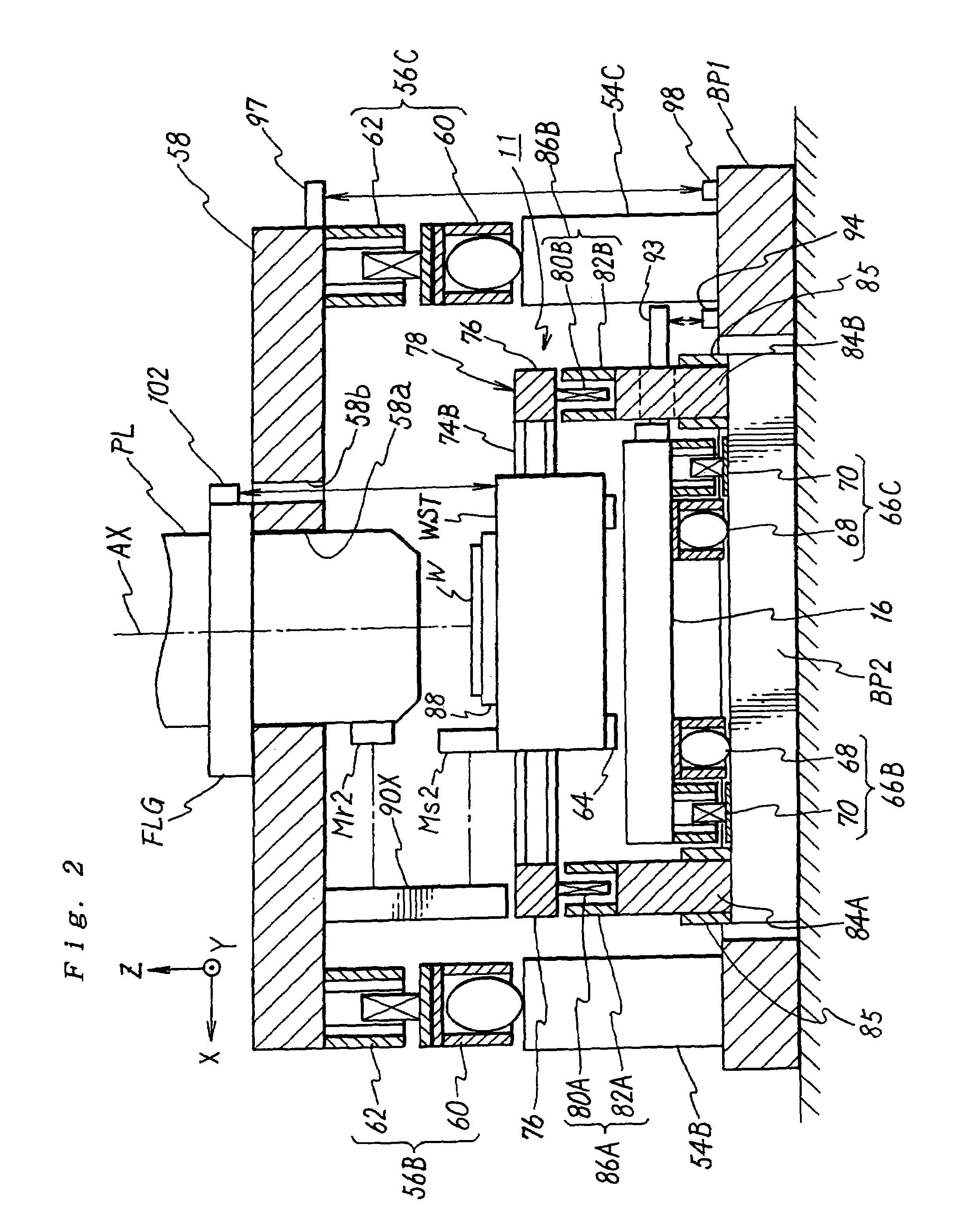
[0178]Next, a description is given of the third embodiment of the present invention with reference to FIGS. 9 and 10. An exposure apparatus of the present third embodiment differs from the exposure apparatus of the above first embodiment, only in the stage unit which holds the wafer W. Therefore, the stage unit is mainly described in the following. It is noted that the same reference numerals are used for components similar or equivalent to those of the first embodiment.

[0179]FIG. 9 shows a perspective view of a stage unit 160 constituting the exposure apparatus according to the third embodiment. The stage unit 160 comprises: the stage supporting bed 16, serving as a stage base, which is horizontally arranged above the second base plate BP2 in FIG. 1 and is held by reaction frames 84C, 84D, 84E, and 84F as first transmitting members consisting of L-shaped members; a Y-stage 162, serving as a first stage, which is disposed onto the upper surface of the stage supporting bed 16; an X-s...


PUM


Abstract

A barrel supporting bed (58) for holding a projection optical system (PL), a driving mechanism (86A, 86B) for driving a stage (WST), a frame (84A, 84B) in which a reaction force caused by driving the stage (WST) is transmitted in a non-contact to the supporting bed (58), and a damping member (85) that is arranged on the frame are provided. Therefore, a vibration and a reaction force, which are caused by the reaction force caused by driving the stage, are damped by the damping member and are transmitted to the earth (set floor), thereby making it possible to effectively reduce a force that is transmitted to the supporting bed from the earth. The frame and the supporting bed have an independent relationship with respect to the vibration, so that the reaction force and the vibration of the frame due thereto exert no direct influence on the projection optical system. This results in suppressing an influence on exposure accuracy which is exerted by vibration of components in an apparatus.

Description

TECHNICAL FIELD[0001]The present invention relates to a stage unit, an exposure apparatus, a device manufacturing method, and a device. More particularly, the present invention relates to a stage unit that is suitable to a precision machine requiring positional controllability of a sample (or a sample stage) with high accuracy, an exposure apparatus used in a lithography process upon manufacturing semiconductor devices (electron devices) such as a semiconductor integrated circuit and a liquid crystal display as the precision machine, an electron device manufacturing method using the exposure apparatus, and a device manufactured by the aforementioned method.BACKGROUND ART[0002]Conventionally, in a lithography process which is a process in manufacturing a semiconductor device, various exposure apparatuses are used to transfer a circuit pattern formed on a mask or a reticle (hereinlater, generically referred to a “reticle”) onto a substrate such as a wafer, or glass plate or the like t...

Claims


Application Information

Patent Timeline
IPC IPC(8): G03B27/62G03B27/42G03B27/58G03F7/20
CPCG03F7/709G03F7/70716
Inventor TAKAHASHI, MASATO
Owner NIKON CORP
Why Eureka
Try Eureka