Water jet pump

a technology of water jet pumps and pumps, which is applied in the field of water jet pumps, can solve the problems of consequently lowering the pump efficiency, and achieve the effect of reducing cavitation and improving pump efficiency

Inactive Publication Date: 2006-02-21
HONDA MOTOR CO LTD
View PDF7 Cites 2 Cited by
  • Summary
  • Abstract
  • Description
  • Claims
  • Application Information

AI Technical Summary

Benefits of technology

[0009]It is therefore an object of the present invention to solve the above-described problems and provide a water jet pump which reduces cavitation and thereby allows an improvement in pump efficiency.
[0014]This reduces the occurrence of cavitation and resultantly improves the pump efficiency.
[0015]In addition, erosion (corrosion), which occurs in the vicinity of the outer circumference of the impeller is also suppressed as a result of the reduced occurrence of cavitation.
[0016]In the case where the bearing of the impeller shaft for supporting the foregoing impeller in the foregoing housing is composed of an angular bearing, the outer diameter of the bearing portion can be reduced.
[0017]By reducing the outer diameter of the impeller, while retaining a pump capacitance (pump performance), the circumferential speed of the outer circumferential surface of the impeller can be reduced. As a result, it becomes possible to further reduce the occurrence of cavitation and further improve the pump efficiency through the combined effect of the edge portion of the outer circumferential surface of the impeller being formed with a radius of curvature.
[0018]By adjusting the size of the foregoing radius of curvature to 0.5 mm or less, it becomes possible to reduce the occurrence of cavitation, while preventing pressure leakage, and more positively improve the pump efficiency.

Problems solved by technology

As a result, cavitation is likely to occur due to a large pressure variation and air bubbles resulting from the cavitation enter the space behind the impeller 1, which causes the problem that the pump efficiency is resultantly lowered.
However, the provision of such a connecting portion has a drawback in that it lowers the pump efficiency accordingly.

Method used


Image

  • Water jet pump
  • Water jet pump
  • Water jet pump

Examples


Embodiment Construction

[0028]The present invention will now we described with reference to the accompanying drawings, wherein the same or similar elements have been identified by the same reference numeral throughout the several views.

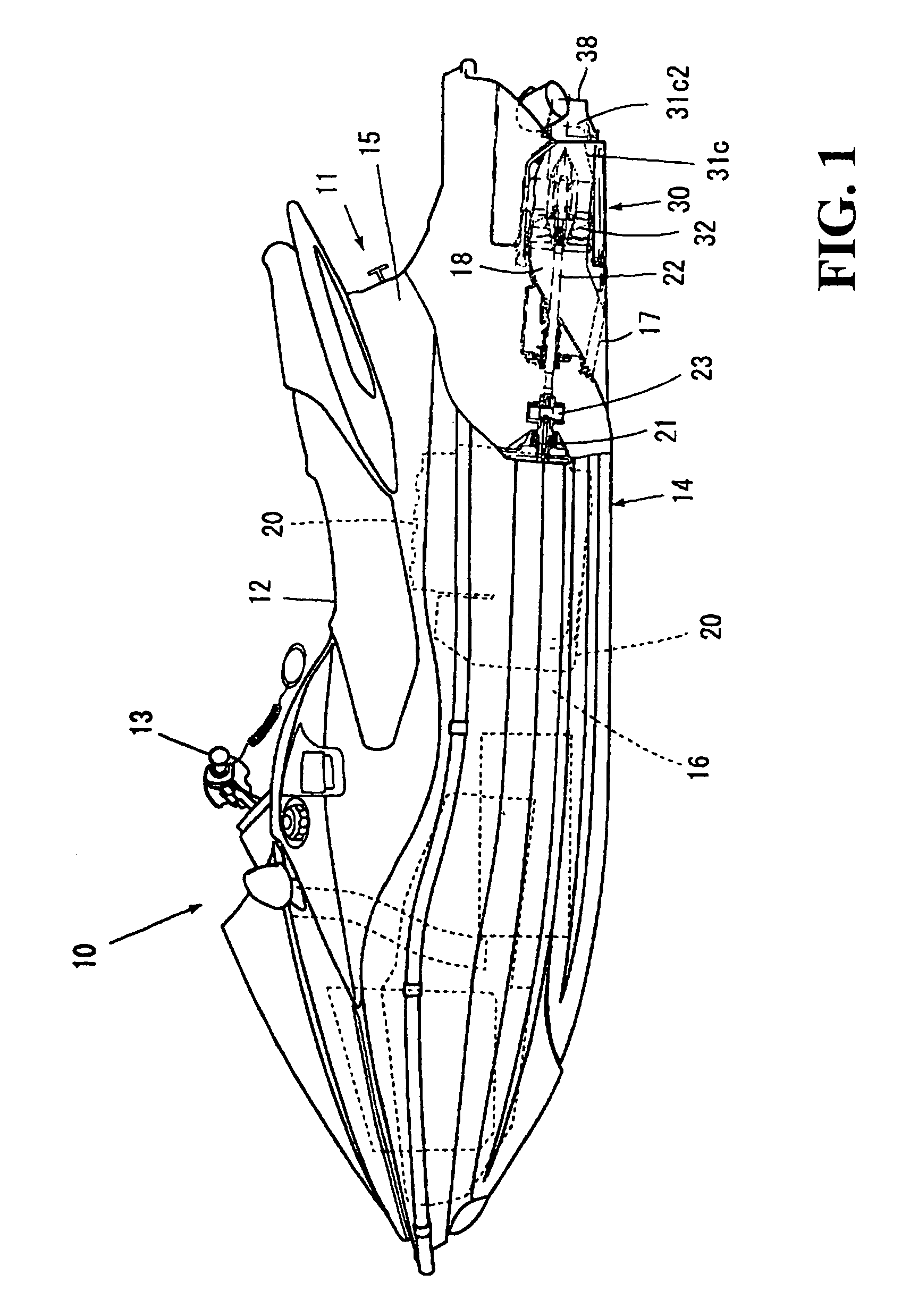
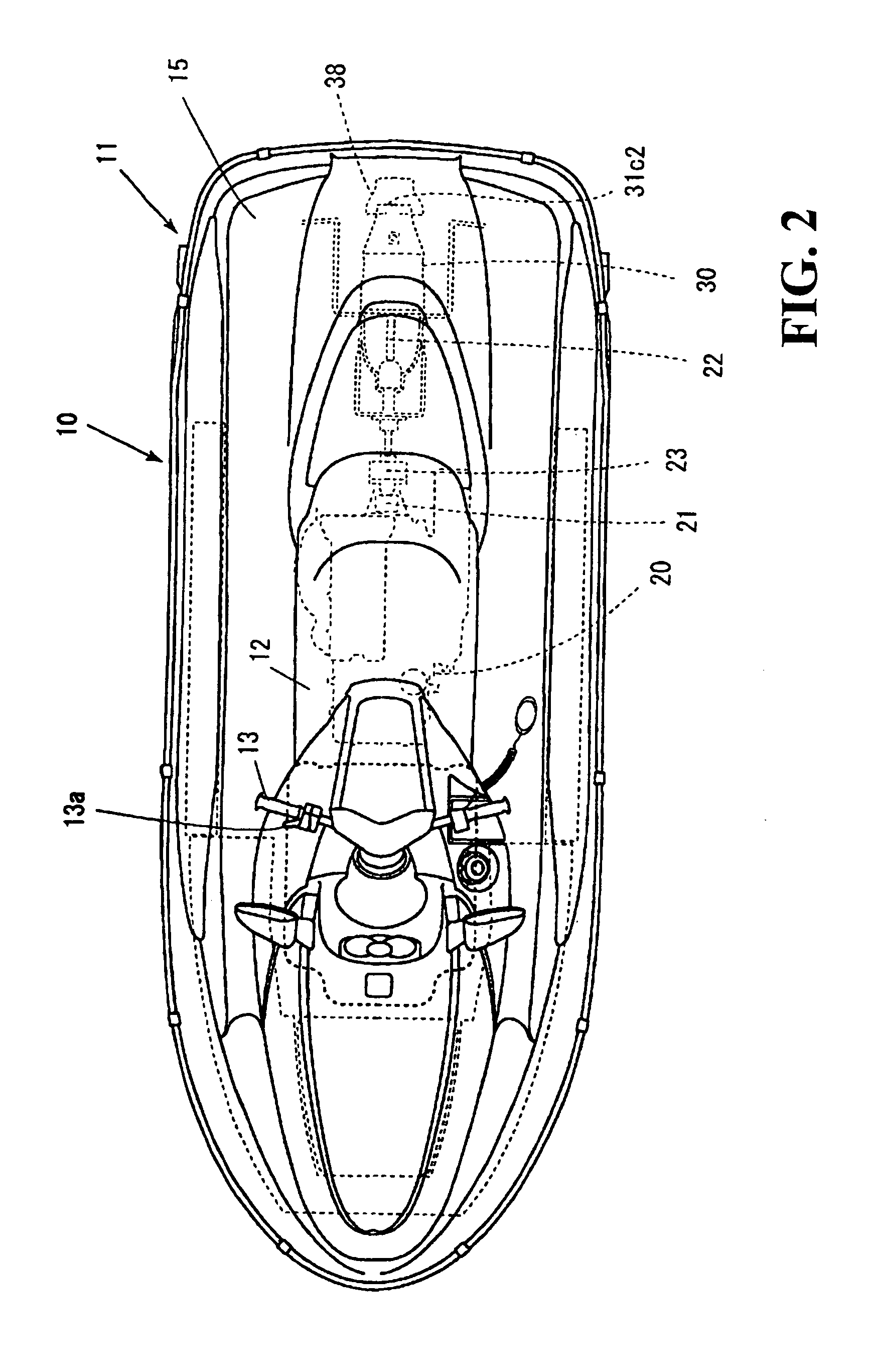
[0029]FIG. 1 is a partially cutaway schematic side view showing an example of a small planing craft or vessel using an embodiment of a water jet pump of the present invention. FIG. 2 is a schematic plan view of the same planing craft.

[0030]As shown in these drawings (primarily in FIG. 1), the small planing craft 10 is a small ship that is mounted by an operator. The small ship is operable by the operator sitting on a seat 12 on a body 11 and gripping a steering handle 13 with a throttle lever.

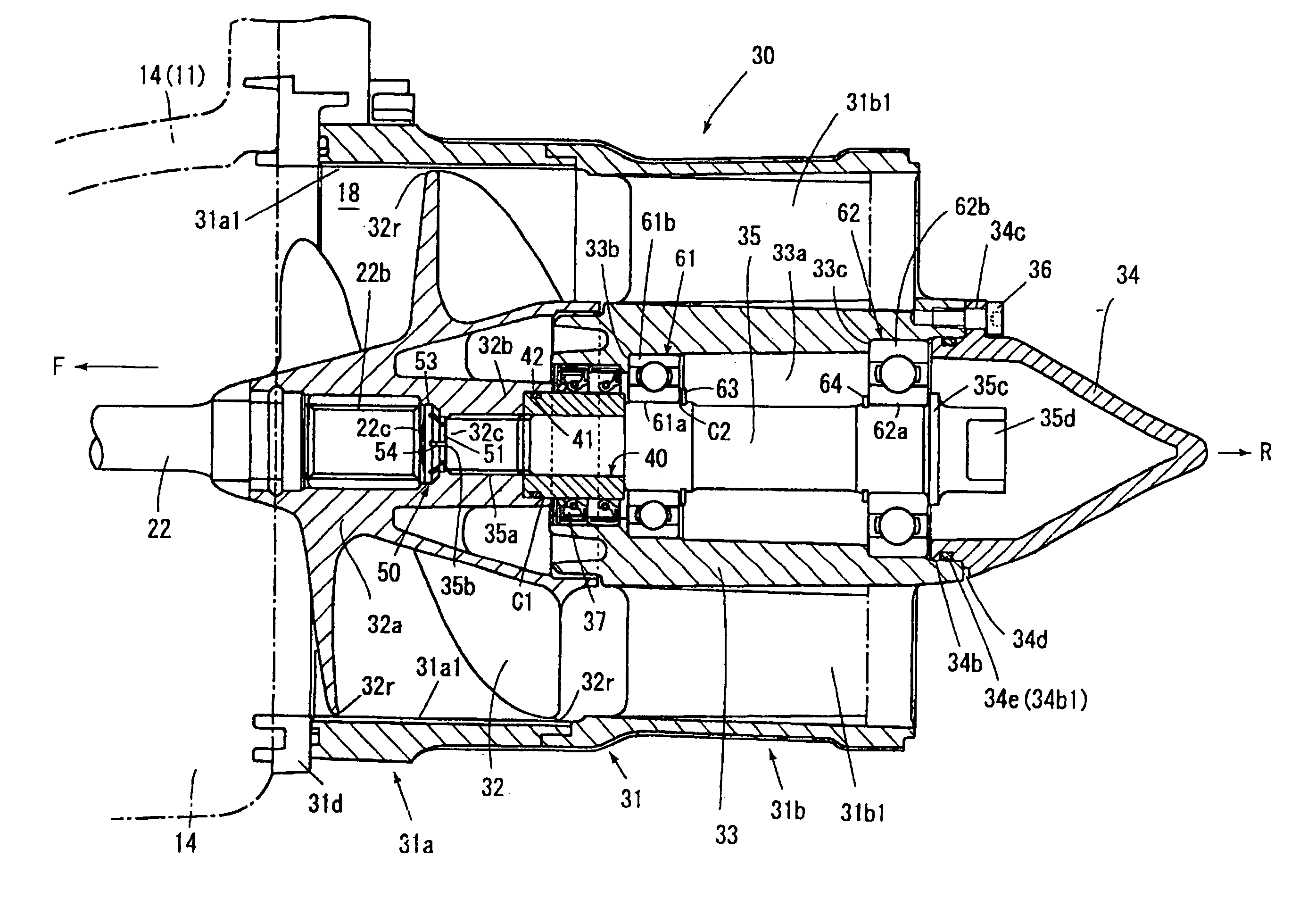
[0031]The body 11 has a floating structure composed of a hull 14 and a deck 15 joined to each other with a space 16 formed inside. In the space 16, an engine 20 is mounted on the hull 14 and a water jet pump 30 is provided as propelling means driven by the engine 20. The jet pump 30 is ...


PUM


Abstract

A water jet pump is provided which reduces cavitation and thereby allows an improvement in pump efficiency. In a water jet pump in which an impeller driven for rotation and is provided in a cylindrical housing, an edge portion of the outer circumferential surface of the impeller that opposes the inner surface of the housing is formed with a radius of curvature. This structure reduces a variation in the pressure of a water stream passing between the outer circumferential surface of the impeller and the inner surface of the housing toward the impeller front surface side, thereby reducing the occurrence of cavitation and improving the pump efficiency.

Description

CROSS-REFERENCE TO RELATED APPLICATIONS[0001]This nonprovisional application claims priority under 35 U.S.C. § 119(a) on patent application No. 2003-305775, filed in Japan on Aug. 29, 2003, the entirety of which is incorporated herein by reference.BACKGROUND OF THE INVENTION[0002]1. Field of the Invention[0003]The present invention relates to water jet pumps (hereinafter also simply referred to as jet pumps). More specifically, the present invention relates to a jet pump used as a propelling device for a ship and, in particular, to anti-cavitation technology.[0004]2. Description of Background Art[0005]In the background art, a jet pump is known to include an impeller, which is driven for rotation and is provided in a cylindrical housing (see, e.g., Japanese Laid-Open Patent Publication No. 2003-89394 (Abstract, FIG. 3) and Japanese Laid-Open Patent Publication No. 2002-87385 (Abstract, FIGS. 1 to 4)). With the impeller being driven for rotation, a jet stream of water occurs to propel...

Claims


Application Information

Patent Timeline
Patent Type & Authority Patents(United States)
IPC IPC(8): B63H11/00B63B35/73B63H11/08B63H23/32F04D29/18
CPCB63H11/08F04D29/181B63H2011/081
Inventor FUSE, TOMOHIROIWAKAMI, HIROSHITSUCHIYA, MASAHIKO
Owner HONDA MOTOR CO LTD
Why Eureka
Try Eureka