Spot welding system and method of controlling pressing force of spot welding gun

Active Publication Date: 2006-02-21
FANUC LTD
View PDF10 Cites 19 Cited by
  • Summary
  • Abstract
  • Description
  • Claims
  • Application Information

AI Technical Summary

Benefits of technology

[0018]The present invention provides a spot welding system using a servo spot welding gun and a control method of a pressing force of the servo spot welding gun, which are

Problems solved by technology

Therefore, there arises a problem of failing in applying a constant pressing force on the objects of welding by the welding tips in accordance with a

Method used


Image

  • Spot welding system and method of controlling pressing force of spot welding gun
  • Spot welding system and method of controlling pressing force of spot welding gun
  • Spot welding system and method of controlling pressing force of spot welding gun

Examples


Embodiment Construction

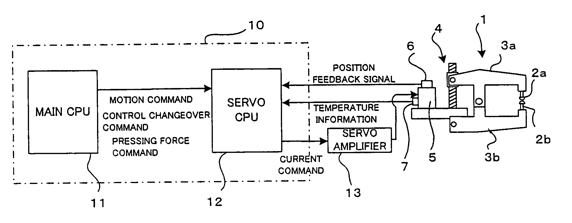
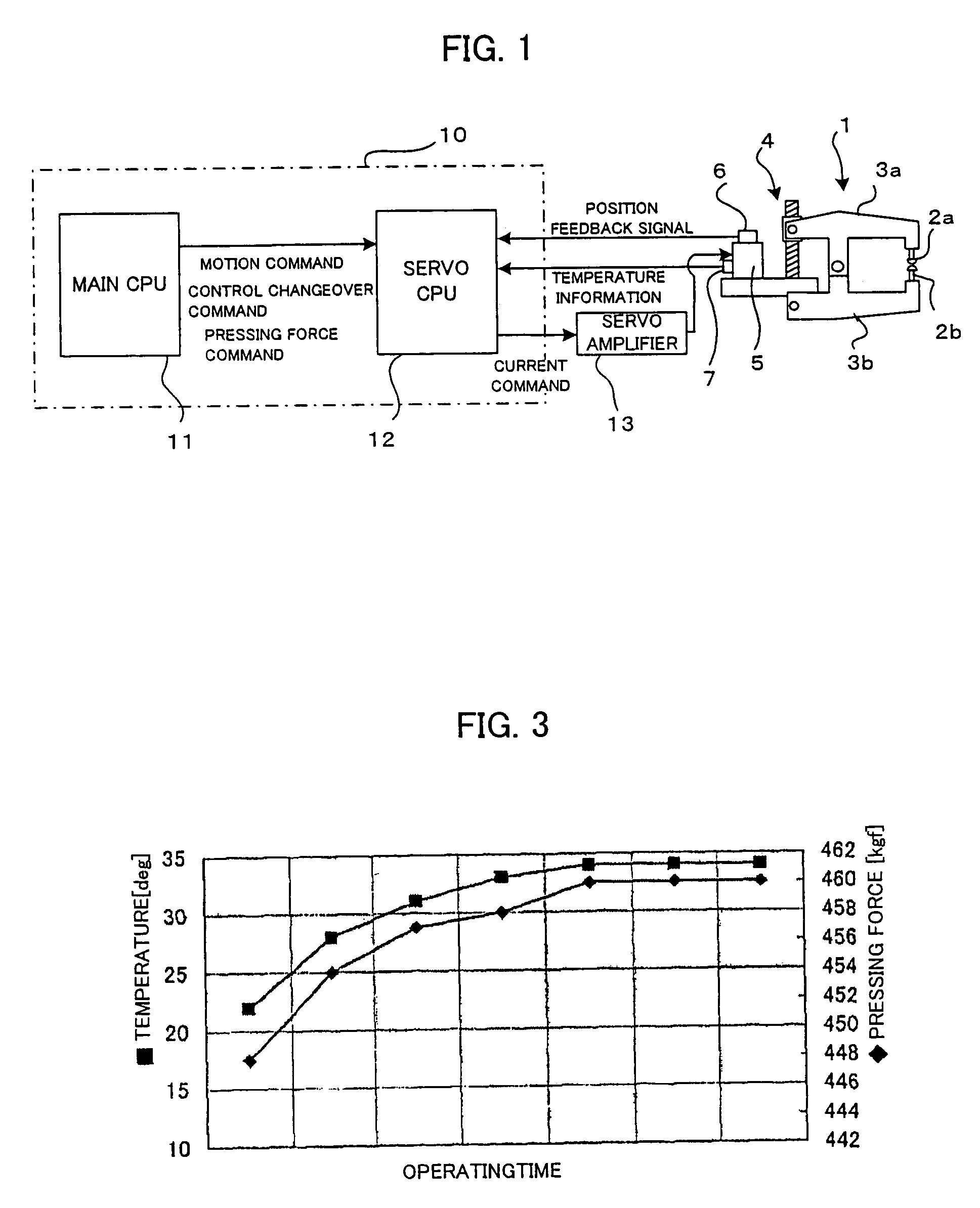
[0026]In the servo spot welding gun in which welding tips are driven by a servomotor, the torque constant of the servomotor and also friction loss of movable components of the driving force transmission mechanism by influence of heat generation in the spot welding gun. Therefore, the pressing force applied on the objects of welding from the welding tips varies in dependence on the temperature of the servomotor and the movable components of the spot welding gun even in a condition of a constant driving current of the servomotor (the same pressing force command). Experiments have been conducted in which the temperature and the pressing force of the spot welding gun are measured in performing spot welding operations repeatedly under conditions of a constant driving current in the servomotor and a constant welding current between the welding tips. Results of the experiments are shown in FIG. 3.

[0027]As shown in FIG. 3, the pressing force by the welding tips increases as the temperature ...


PUM

PropertyMeasurementUnit
Temperatureaaaaaaaaaa
Forceaaaaaaaaaa

Abstract

A spot welding system using a spot welding gun having a servomotor for driving welding tips capable of suppressing variation of pressing force due to influence of heat generated by welding current to obtain an uniform pressing force. A difference between the temperature T detected by a temperature sensor and an initial temperature T0 is multiplied by a coefficient A to obtain a pressing force compensation amount α. A pressing force d estimated by an observer is subtracted from the compensated command pressing force p′ and an obtained difference is multiplied by a constant K2 to obtain a torque command (current command) τ for driving the servomotor to press the objects by the welding tips. Since the commanded pressing force is compensated in accordance with the temperature, a constant and stable pressing force is produced without influence of the temperature variation.

Description

BACKGROUND OF THE INVENTION[0001]1. Field of the Invention[0002]The present invention relates to a spot welding system using a spot welding gun driven by a servomotor and a method of controlling a pressing force of the spot welding gun.[0003]2. Description of Related Art[0004]In performing a spot welding operation using a spot welding gun, objects of welding such as metal plates are clamped and pressed by a pair of welding tips of the spot welding gun and an electric current is flown between the welding tips through the objects to be fused together by Joule heat generated by the electric current. A spot welding gun using a servomotor for driving the welding tips is known as a servo welding gun.[0005]FIG. 4 schematically shows a conventional welding system using the servo welding gun in which the welding tips are driven by a servomotor.[0006]The spot welding gun 1 comprises arms 3a, 3b having welding tips 2a, 2b respectively at distal ends thereof, a ball screw / nut mechanism 4 for co...

Claims


Application Information

Patent Timeline
IPC IPC(8): B23K11/24B23K11/11B23K11/25B23K11/28B23K11/31
CPCB23K11/25B23K11/252B23K11/314B23K11/31B23K11/311B23K11/255
Inventor KATO, TETSUAKIOKANDA, KOICHIARITA, SOICHI
Owner FANUC LTD
Why Eureka
Try Eureka