
Tuning circuit for a filter

a filter and circuit technology, applied in the direction of pulse manipulation, pulse technique, line-transmission details, etc., can solve the problems of incorrect tuning or trimming of the filter stage, and the overall production cost of the overall chip is considered to be much higher, so as to achieve the effect of low space and high degree of accuracy in the tuning of the filter stag

Active Publication Date: 2006-02-21
MAXLINEAR INC
View PDF13 Cites 64 Cited by
  • Summary
  • Abstract
  • Description
  • Claims
  • Application Information

AI Technical Summary

Benefits of technology

[0014]The object of the present invention is therefore to provide a tuning circuit for tuning a filter stage, which occupies as little space as possible during integration and which ensures a high degree of accuracy in the tuning of the filter stage.
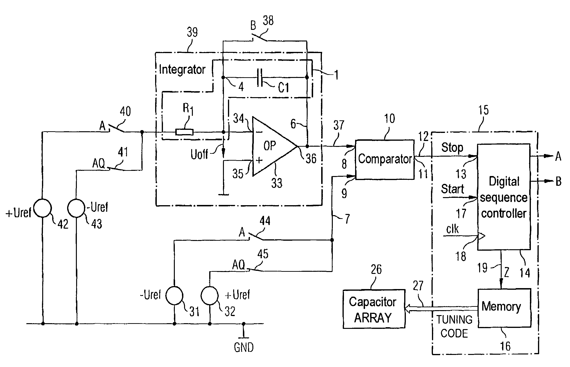
[0017]with the RC time constant (τ) being the product of the resistance of a resistor (R1) in the RC element and the capacitance of a capacitor (C1), which is connected in series with the resistor (R1), in the RC element, having a comparator for comparison of the voltage which is produced at the potential node between the resistor (R1) and the capacitor (C1), with a reference ground voltage, and having a controller which varies the charge on the capacitor (C1) in the RC element until the comparator indicates that the voltage which is produced at the potential node is equal to the reference ground voltage, with the controller switching a capacitor array as a function of the charge variation time, which capacitor array is connected in parallel with the capacitor (C1) in the RC element, in order to compensate for any discrepancy between the RC time constant (τ) of the RC element and a nominal value.

Problems solved by technology

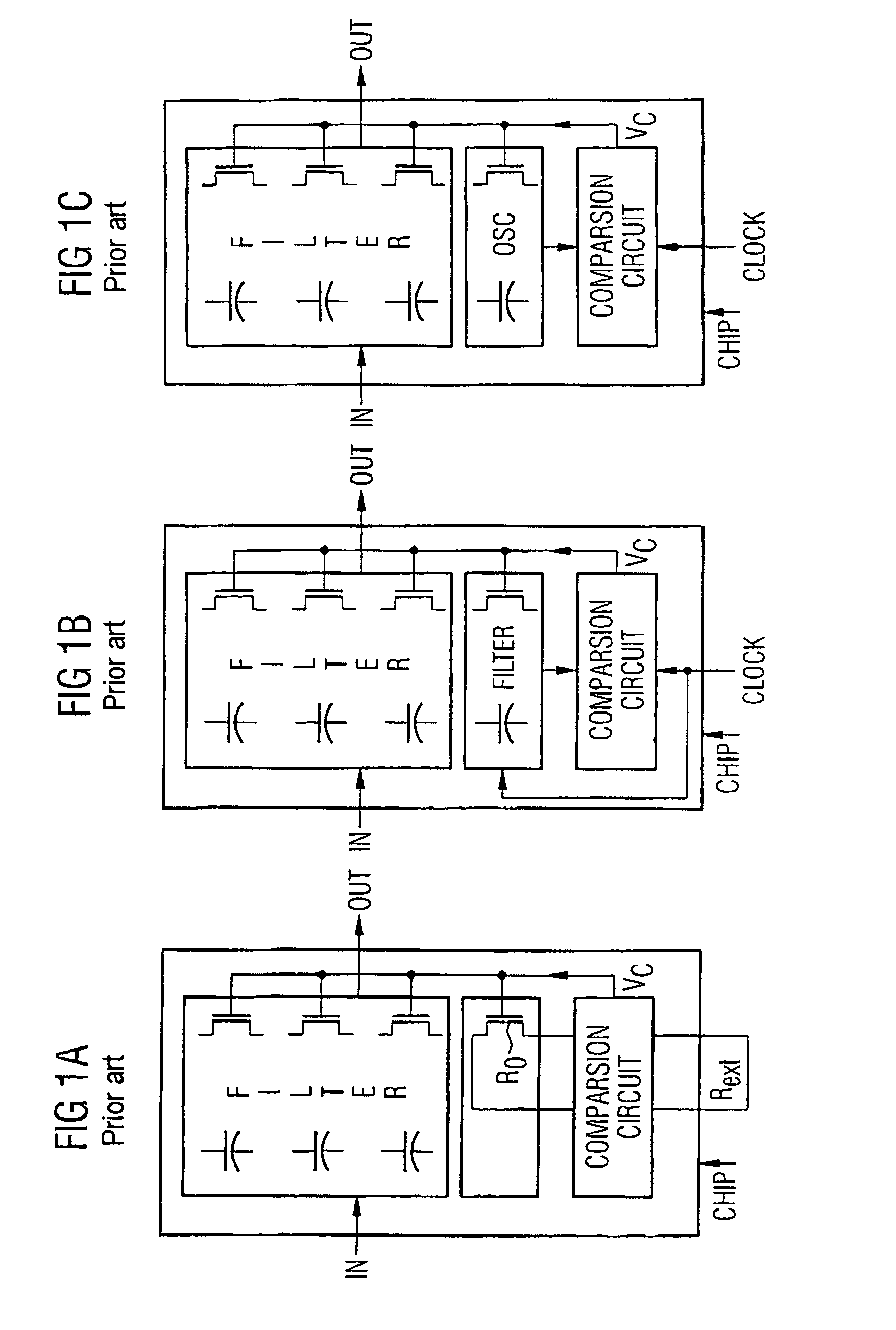
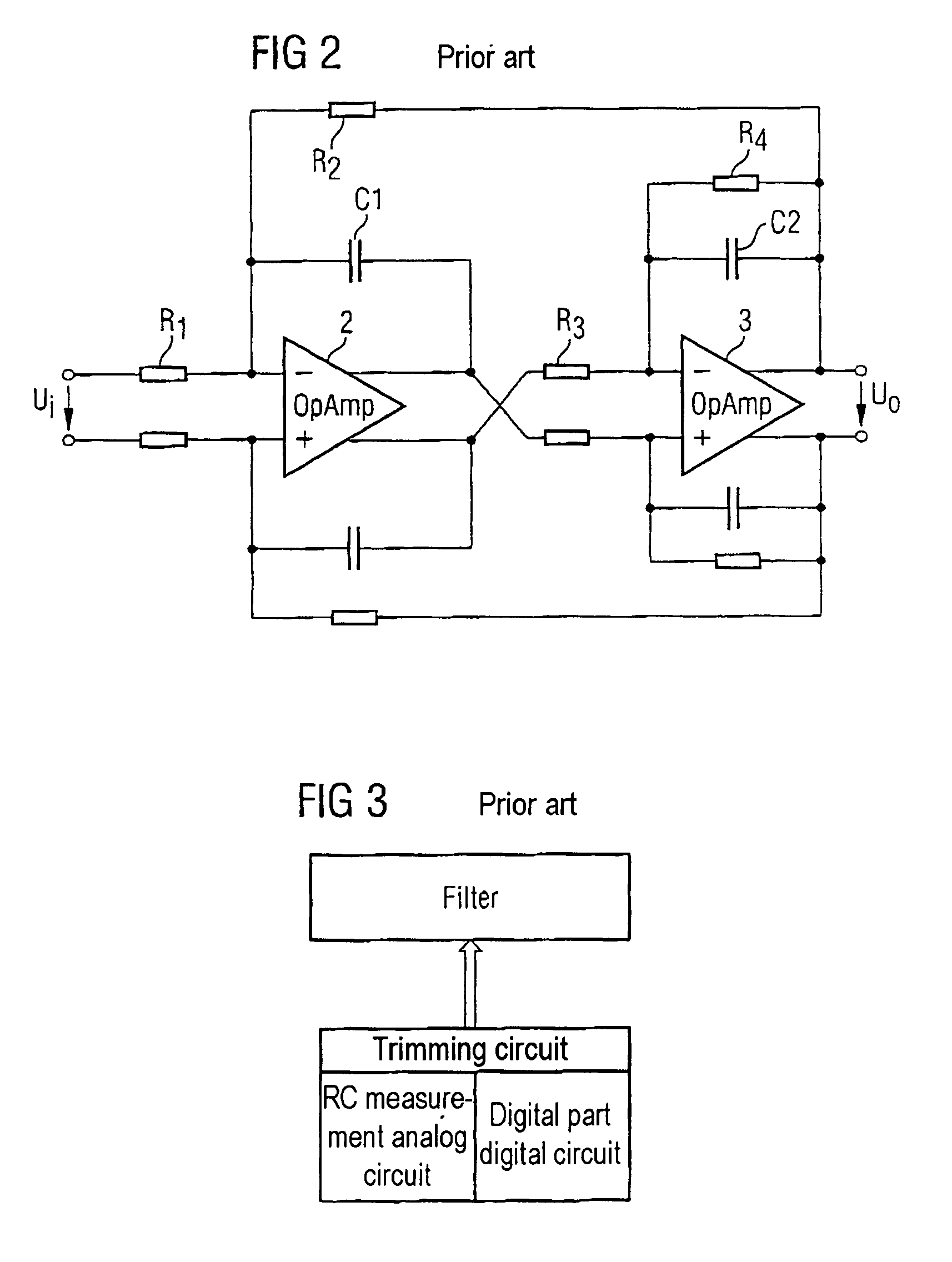
When the filters are integrated on a semiconductor chip, process discrepancies occur during the production process, so that the resistance and capacitance values of the RC elements contained in the filter may not be the same as the desired nominal value.
The additional space required leads to considerably higher production costs for the overall chip.
This in turn results in the filter stage being tuned or trimmed incorrectly.

Method used


Image

  • Tuning circuit for a filter
  • Tuning circuit for a filter
  • Tuning circuit for a filter

Examples


Embodiment Construction

[0074]FIG. 4 shows a circuit arrangement in order to explain a first embodiment of the tuning circuit according to the invention. A filter 3 to be tuned contains a first RC element 1 and a second RC element 2. The filter 3 has further circuit components, which are not illustrated in FIG. 4, in addition to the first and second RC elements. The filter 3 is supplied with voltage by means of a positive supply voltage Vdd and by means of a negative supply voltage Vss. The first RC element 1 comprises a resistor R1 and a capacitor C1, which is connected in series with it. In the same way, the second RC element 2 comprises a capacitor C2 and a resistor R2, which is connected in series with it. A connecting node 4 within the first RC element 1, at which the resistor R1 and the capacitor C1 in the RC element 1 are connected to one another, and a connecting node 5 within the second RC element 2, at which the capacitor C2 in the second RC element 2 and the resistor R2 in the second RC element ...


PUM


Abstract

The invention relates to a tuning circuit for tuning a filter stage, which has an RC element (1) with an RC time constant (τ), with the RC time constant (τ) being the product of the resistance of a resistor (R1) in the RC element (1) and the capacitance of a capacitor (C1), which is connected in series with the resistor (R1), in the RC element (1), having a comparator (10) for comparison of the voltage which is produced at the potential node (4) between the resistor (R1) and the capacitor (C1), with a reference ground voltage; and having a controller (15) which varies the charge on the capacitor (C1) in the RC element (1) until the comparator (10) indicates that the voltage which is produced at the potential node (4) is equal to the reference ground voltage, with the controller (15) switching a capacitor array (26) as a function of the charge variation time, which capacitor array (26) is connected in parallel with the capacitor (C1) in the RC element (1), in order to compensate for any discrepancy between the RC time constant (τ) of the RC element (1) and a nominal value.

Description

TECHNICAL FIELD[0001]The invention relates to a tuning circuit for a filter, in order to tune a filter stage.BACKGROUND ART[0002]As the amounts of data involved rise ever further, the frequency separations between individual transmission frequency bands become ever narrower. In consequence, ever more accurate analog anti-aliasing filters are required. For data transmission, the data from a data source is converted by means of a digital / analog converter to an analog transmission signal, and is transmitted to a receiver via a data transmission channel. In the receiver, the received data is converted to digital data by means of a digital / analog converter, for further data processing. The analog anti-aliasing filters prevent the analog / digital converter and digital / analog converter from injecting undesirable signal interference into the transmission signal. The filters are generally integrated on a semiconductor chip. The analog anti-aliasing filters contain RC elements which comprise r...

Claims


Application Information

Patent Timeline
Patent Type & Authority Patents(United States)
IPC IPC(8): H03K5/00H03H11/12H03H19/00
CPCH03H11/1291H03H2210/043H03H2210/021H03H19/008
Inventor GAGGL, RICHARDNOPP, MANFREDPESSL, PETERSCHRANZ, CHRISTIANSTRAUSSNIGG, DIETMAR
Owner MAXLINEAR INC
Learn More