Polarization division duplexing with cross polarization interference canceller

a cross-polarization interference canceller and polarization division technology, applied in the direction of line-fault/interference reduction, amplitude demodulation, pulse technique, etc., can solve the problems of achieving more bandwidth-efficient modulation, requiring more complex and expensive hardware, and limited capacity of current wireless systems, so as to effectively take advantage of frequency reuse

Inactive Publication Date: 2006-02-21
THE BOEING CO
View PDF16 Cites 18 Cited by
  • Summary
  • Abstract
  • Description
  • Claims
  • Application Information

AI Technical Summary

Benefits of technology

[0011]The present invention provides a full duplex telecommunication system that effectively takes advantage of frequency reuse using circular polarization. The present invention also provides a mechanism that will detect whether or not

Problems solved by technology

Capability of current wireless systems is limited due to smaller channel bandwidth allocations, typically less than 100 MHz (mega hertz, or million cycles per second), available in the Federal Communications Commission (FCC) allocated frequency bands in the range of 1 to 40 GHz.
Even at higher frequencies and with wider channel bandwidth allocations, however, there still exist economic, technical, and other incentives to make the most efficient use of the allocated channel bandwidth because, for example, of the limited availability of such channel bandwidth allocations, their licensing cost, and operating costs to use them.
Achieving more bandwidth-efficient modulation presents several technical challenges, however, and typically requires more complex and expensive hardware.
A

Method used


Image

  • Polarization division duplexing with cross polarization interference canceller
  • Polarization division duplexing with cross polarization interference canceller
  • Polarization division duplexing with cross polarization interference canceller

Examples


Embodiment Construction

[0022]The following detailed description is of the best currently contemplated modes of carrying out the invention. The description is not to be taken in a limiting sense, but is made merely for the purpose of illustrating the general principles of the invention, since the scope of the invention is best defined by the appended claims.

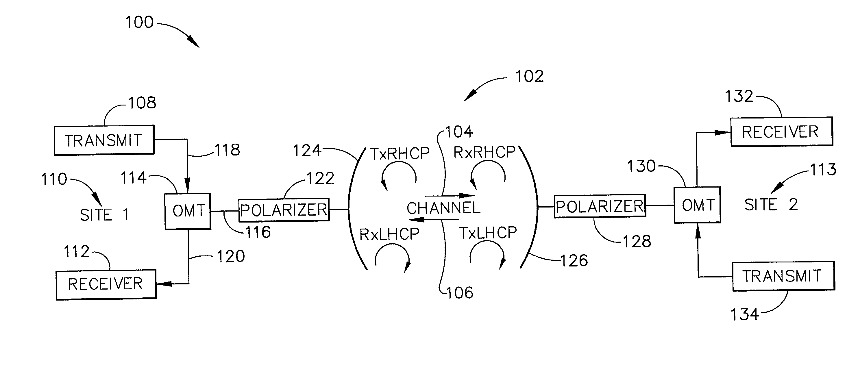
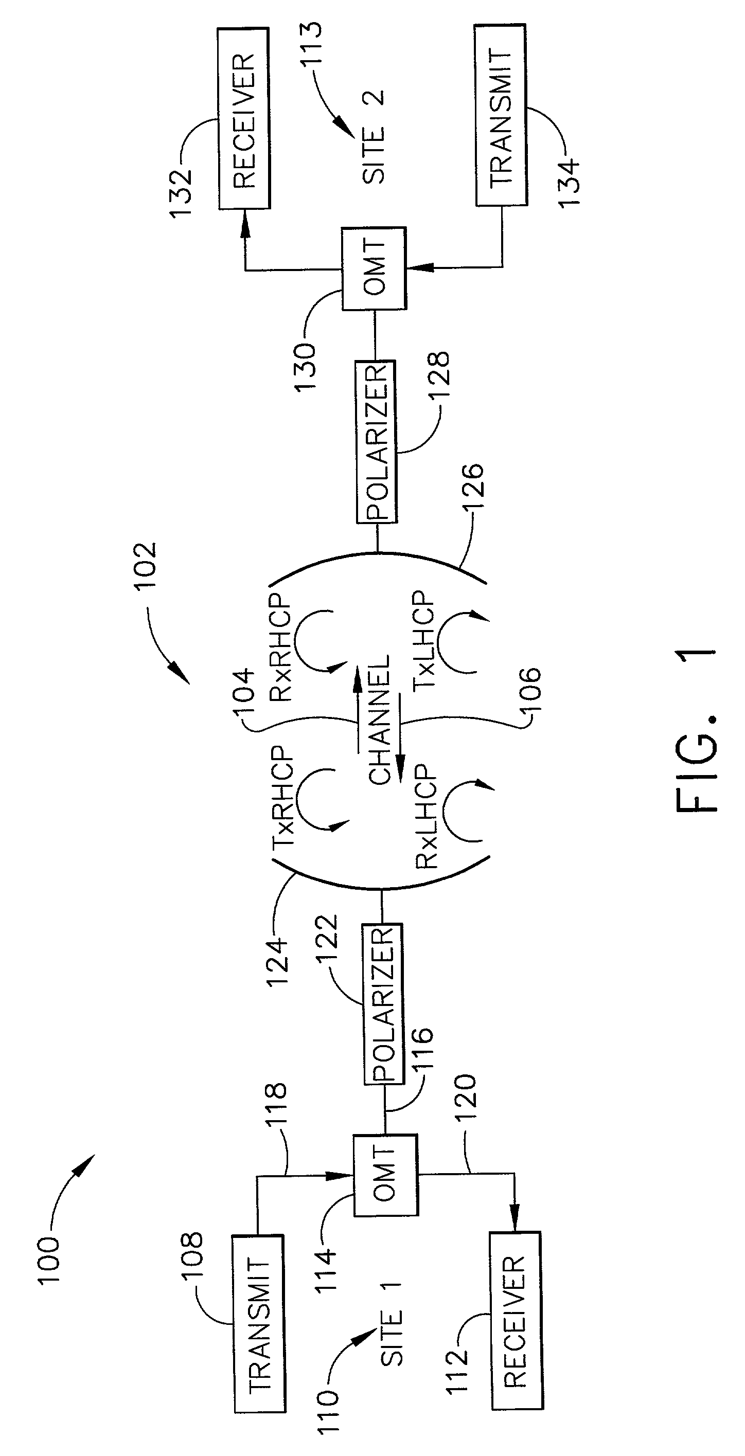
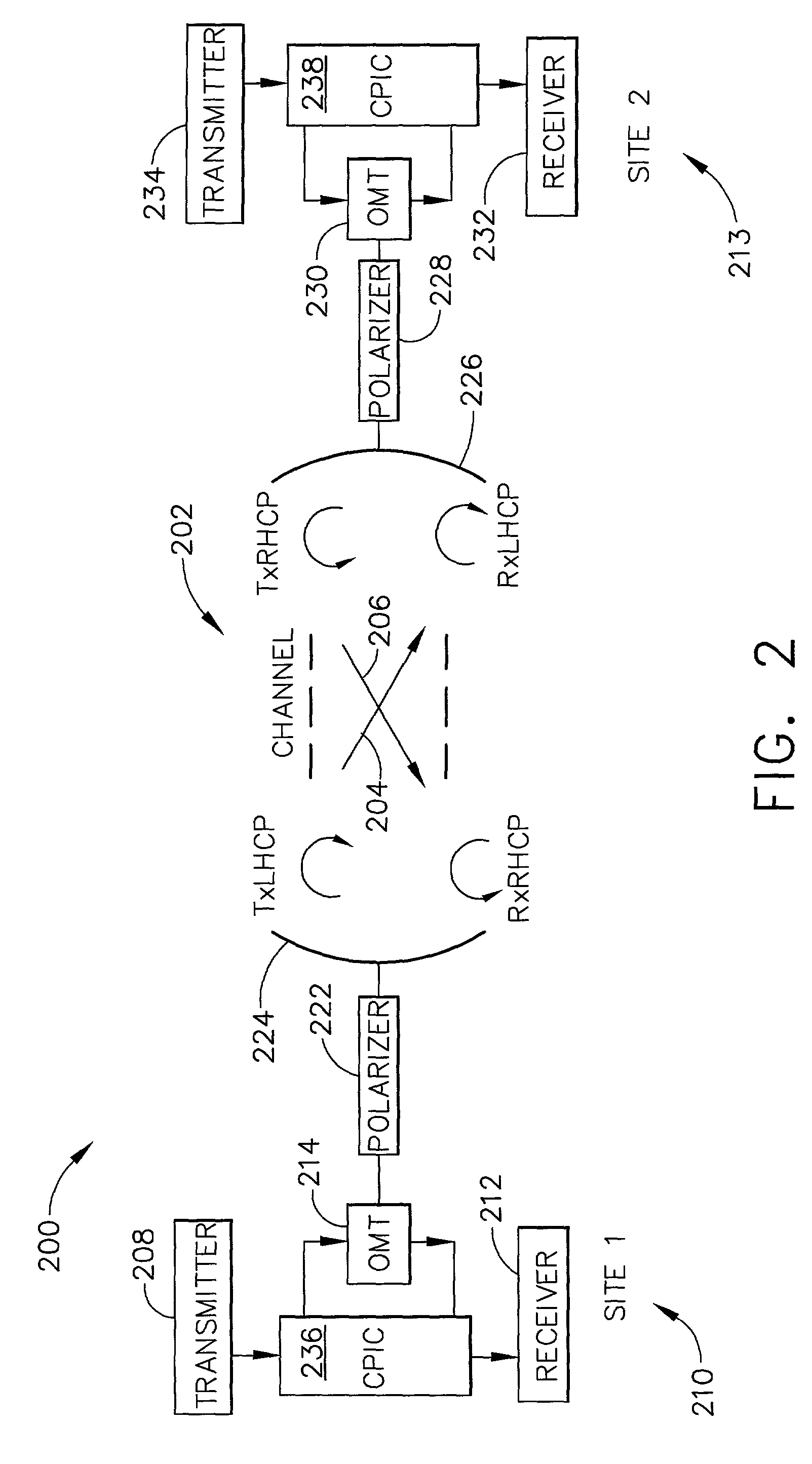
[0023]The present invention provides a full duplex telecommunication system that effectively takes advantage of frequency reuse using circular polarization. One embodiment of the present invention takes advantage of frequency reuse by implementing polarization division duplexing (PDD) for a full duplex wireless telecommunication system. Polarization division duplexing according to one embodiment uses opposite circular polarizations for forward and return links to separate transmit and receive signals at each site, for example, by transmitting a forward link on one circular polarization and receiving the return link on the opposite polarization at a site...


PUM


Abstract

A telecommunication system includes a transmitter configured to modulate a forward link RF carrier with a first set of data; a receiver configured to demodulate a second set of data from a return link RF carrier; an orthomode transducer having two linear ports and a circular waveguide port, where one of the linear ports is connected as an input from the transmitter and another linear port is simultaneously connected as an output to the receiver; an antenna; and a linear-to-circular polarizer connected to the circular waveguide port and connected to the antenna, where the linear-to-circular polarizer is configured so that a first linear polarization at the circular waveguide port results in a first circular polarization at the antenna and a second circular polarization at the antenna results in a second linear polarization at the circular waveguide port.

Description

BACKGROUND OF THE INVENTION[0001]The present invention generally relates to point-to-point high frequency, high data rate wireless telecommunication systems and, more particularly, to band efficient communications using polarization division duplexing.[0002]There is an increasing need for very high data rates, over 300 Mbps (megabits per second), in wireless telecommunication systems. High data transmission rates are needed, for example, in backhaul networks, LMDS (local multipoint distribution service), MMDS (multichannel or microwave multipoint distribution service), dedicated links in campus networks, private communication networks, and high speed internet services such as cable modems and DSL (digital subscriber line). In areas without gas or steam pipes or other underground conduits, it is less costly to set up wireless transceivers on rooftops than to dig up the ground to install optical fiber. Installation of a wireless link requires only the placement of antennas and associa...

Claims


Application Information

Patent Timeline
IPC IPC(8): H03D1/04H03K5/01H04B1/10H04L1/00H03D1/06H03K5/00H04B1/00H04B1/52H04J99/00
CPCH04J15/00H04B1/525H04J99/00
Inventor BACH, SUSAN E.LOHEIT, KURT W.HIRAMOTO, REMY O.
Owner THE BOEING CO
Why Eureka
Try Eureka