Cladding-pumped optical fiber and methods for fabricating

a technology of cladding and optical fiber, applied in the field of cladding pumped fiber optic articles, can solve the problems of low absorption per unit length of optical fiber devices, detracting from the performance of optical fiber lasers or amplifiers, and pushing radiation, and achieve the effect of reducing the depth of indentations or depressions

Inactive Publication Date: 2006-02-21
NUFERN
View PDF52 Cites 20 Cited by
  • Summary
  • Abstract
  • Description
  • Claims
  • Application Information

AI Technical Summary

Benefits of technology

[0011]It is considered that the combination of the straight and inwardly curved sections in the outer circumference of the cladding enhances scattering of the pump radiation for more effective absorption of the pump radiation by the core. For example, the inwardly curved section can intercept the pump light reflected from the straight section in a substantially different direction, thus achieving a higher degree of randomization of the paths of the light rays of the pump light for increased interception of the light by the core of the optical fiber article.
[0016]In one aspect, the invention provides a method of making an optical fiber article having an optical fiber core and an optical fiber cladding surrounding the optical fiber core. The method can include the following steps: providing a preform having a preform core and a preform cladding surrounding the preform core, where the preform core includes a rare earth material and has a selected index of refraction, and the preform cladding has an index of refraction less than the selected index of refraction; forming at least one slot in the preform cladding; forming at least one flat area in the preform cladding; and drawing the preform to form the optical fiber article such that the optical fiber article includes an optical fiber core surrounded by an optical fiber cladding having an index of refraction that is less than the index of refraction of the optical fiber core, and wherein the optical fiber cladding includes an outer circumference having at least one inwardly curved section and at least one straight section. In another aspect of the invention, the preform can be drawn at a higher temperature more conducive to providing a lower attenuation and higher strength optical fiber article.
[0017]A glass jacket, having an index of refraction that is less than the index of refraction of the preform cladding, can be disposed about the preform cladding and drawn with the preform to provide an optical fiber article having a glass outer layer surrounding the cladding. The glass jacket can be collapsed, such as by heating, onto the preform cladding. The outer circumference of the glass jacket can be shaped, such as to reduce the depth of indentations or depressions in the glass jacket.

Problems solved by technology

In such optical fiber lasers and amplifiers, the pump radiation can be introduced directly to the core, which can be difficult due to the small size of the core, or can be introduced to the cladding surrounding the core and absorbed by the core as the rays propagating in the cladding intersect the core.
Unfortunately, when the cladding has a circular outer circumference, the pump radiation can essentially propagate down the optical fiber while spiraling around the core without substantially intersecting the core.
This leads to a low absorption per unit length of the optical fiber device, and hence detracts from the performance of the optical fiber laser or amplifier.
For example, a fiber having an offset core can be difficult to interconnect with other optical components.
Designs, such as the diamond and polygon designs discussed above, that require the circumference of the cladding to predominately consist of flat areas, can be difficult to fabricate.
A reduced draw temperature typically produces optical fibers having higher attenuation and lower mechanical strength.
In addition, the star shaped configuration disclosed in U.S. Pat. No. 5,949,941 can be difficult to manufacture.

Method used


Image

  • Cladding-pumped optical fiber and methods for fabricating
  • Cladding-pumped optical fiber and methods for fabricating
  • Cladding-pumped optical fiber and methods for fabricating

Examples


Embodiment Construction

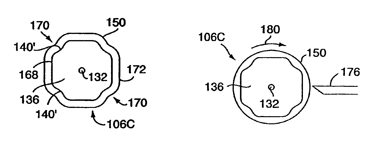
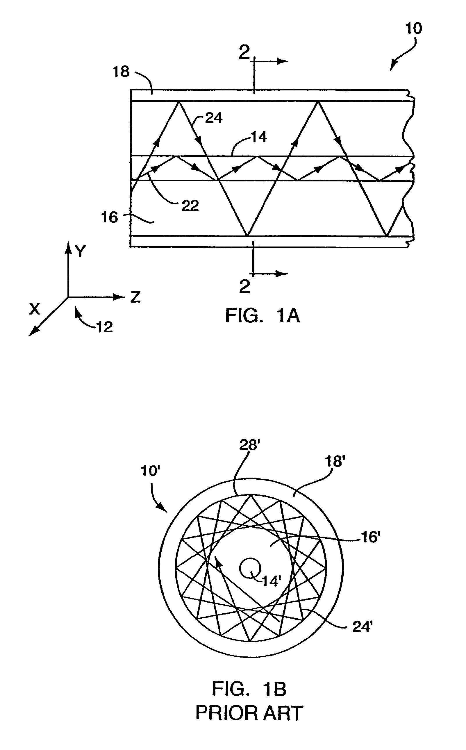
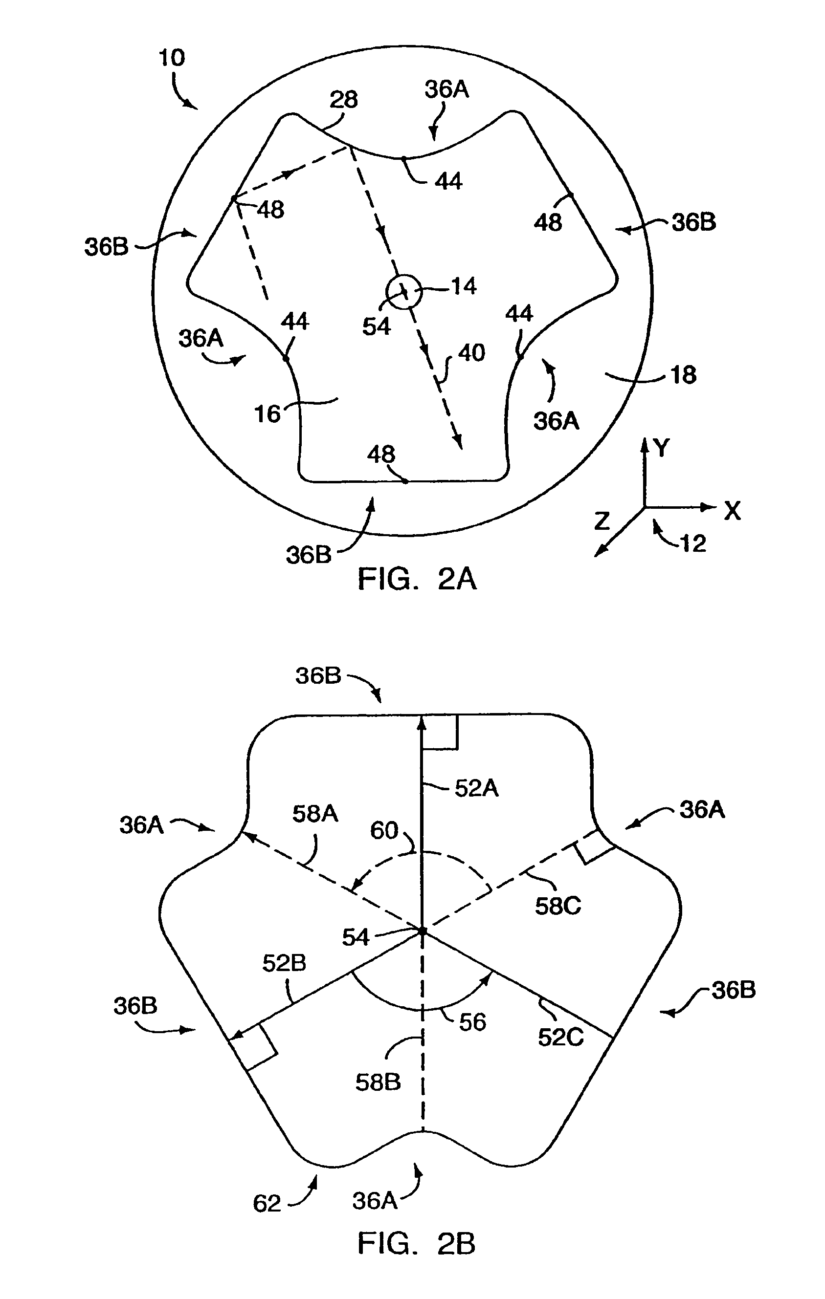
[0038]FIG. 1A is a cross sectional view of an optical fiber article 10 that extends in the longitudinal, or Z, direction, as identified by the coordinate system 12. The optical fiber article 10 includes a core 14, a cladding 16 that surrounds the core 14, and can also include the outer layer 18 that surrounds the cladding 16. The cladding 16 includes a lower index of refraction than the core 14 such that the laser light 22 to be amplified or generated is confined largely to the core 14. The outer layer 18 includes a lower index of refraction than the cladding 16 such that the pump radiation 24 is confined largely to the cladding 16. A second outer layer, which can include a plastic or polymer or other similar material, can surround the outer layer 18 for protecting the optical fiber article 10.

[0039]The core 14 typically includes one or more rare earth dopants, which can be selected from the Lanthanide group of elements in the periodic table, in a glass matrix, which can be a silica...


PUM

PropertyMeasurementUnit
wavelengthaaaaaaaaaa

Abstract

Disclosed is an optical fiber article for receiving pump radiation of a first wavelength for amplifying or generating radiation of a second wavelength. The optical fiber article includes a core for propagating light of the second wavelength. The core has a first index of refraction and includes a rare earth material. A cladding surrounds the core and has a second index of refraction that is less than the first index of refraction. The outer circumference of the cladding can include a plurality of sections, where the plurality of sections includes at least one substantially straight section and one inwardly curved section. The optical fiber article can also include at least one outer layer surrounding the cladding, where the index of refraction of the outer layer is less than the second refractive index. Methods for producing the optical fiber article are also disclosed, as well as methods for providing a preform for drawing such an optical fiber article.

Description

[0001]This application is a continuation of U.S. application Ser. No. 10 / 287,322 filed Nov. 4, 2002, now U.S. Pat. No. 6,779,364 which is a divisional of U.S. application Ser. No. 09 / 694,549, filed Oct. 23, 2000, now issued as U.S. Pat. No. 6,477,307. The foregoing applications are hereby incorporated by reference herein.FIELD OF THE INVENTION[0002]The present invention relates to fiber optic articles and, more particularly, to cladding-pumped fiber optic articles for lasers, amplifiers and the like.BACKGROUND[0003]Optical fiber lasers and amplifiers are known in the art. In such lasers and amplifiers, rare earth materials disposed in the core of the optical fiber laser or amplifier receive pump radiation of a predetermined wavelength and, responsive thereto, provide or amplify light of a different wavelength for propagation in the core. For example, the well known erbium doped fiber amplifier (EDFA) receives pump radiation having a wavelength of 980 or 1480 nanometers (nm) and ampl...

Claims


Application Information

Patent Timeline
Patent Type & Authority Patents(United States)
IPC IPC(8): C03B37/075C03B37/00C03B37/012G02B6/036H01S3/067
CPCC03B37/01211C03B37/01228C03B37/01234G02B6/03633C03B37/01225H01S3/094007C03B2201/10C03B2201/12C03B2201/34C03B2201/50C03B2203/10C03B2203/12C03B2203/23H01S3/067H01S3/06708H01S3/06729
Inventor TANKALA, KANISHKACARTER, ADRIAN
Owner NUFERN
Why Eureka
Try Eureka