Air-to-air heat pump defrost bypass loop

Inactive Publication Date: 2006-02-28
YORK INT
View PDF35 Cites 20 Cited by
  • Summary
  • Abstract
  • Description
  • Claims
  • Application Information

AI Technical Summary

Benefits of technology

[0011]An advantage of the present invention is that the de-icing electric heating elements and the cost associated with its operation may be eliminated.
[0012]A further advantage of the present invention is that the heat pump system can remain in the heating mode during the defrost/de-ice operation, so that the indoor unit continues to operate as a condenser and the outdoor unit continues to operate as an evaporator. It is not necessary to reverse the cycle of the heat pump to place it into the cooling mode to accomplish defrost/de-ice.
[0013]Another advantage of the present invention is that, when used in conjunction with conventional defrosting methods, the defrost c

Problems solved by technology

The formation of the ice thus reduces the performance or efficiency of the heat pump system.
However, while the unit is in such a defrost cycle, it is not providing heat as the refrigerant flow is in the direction for cooling.
If there is still a heat demand required in the space being heated, the heat demand typically

Method used


Image

  • Air-to-air heat pump defrost bypass loop
  • Air-to-air heat pump defrost bypass loop
  • Air-to-air heat pump defrost bypass loop

Examples


example 1

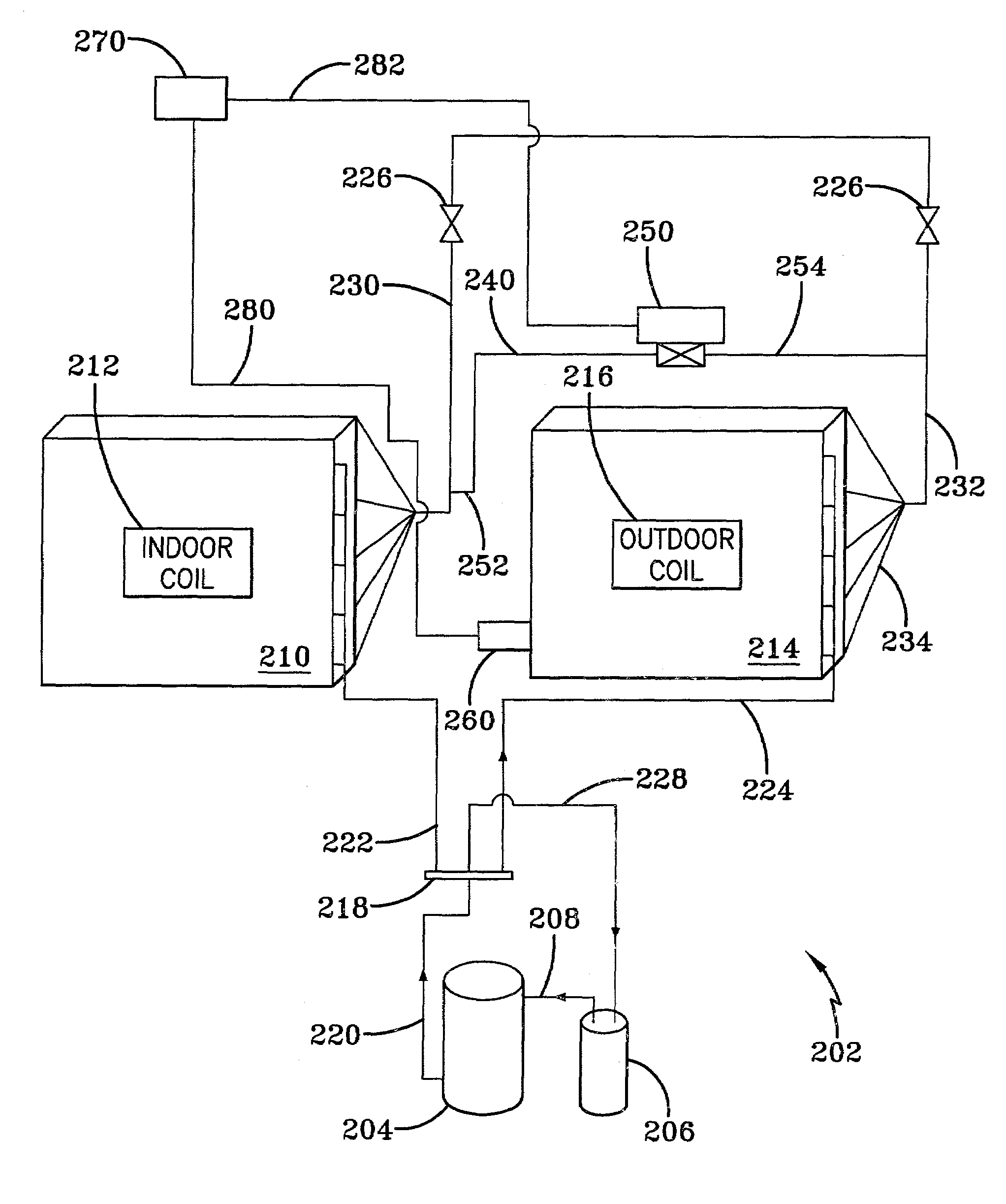
[0027]An air-to-air heat pump system 302, shown in the heating mode, includes a defrost bypass loop 340 as depicted in FIG. 3. A defrost bypass loop 340 connects a refrigerant discharge means, such as a discharge line 330, from the indoor coil unit 310 to the inlet line 332 of the outdoor unit. A bypass line having a first end 352 and a second end 354 connects to discharge line 330 at its first end 352 between indoor coil unit 310 and expansion device 326. A valve 350 is located in bypass line. Bypass line 352, 354 connects to inlet line 332 at its second end 354.

[0028]A temperature sensing device 360 is placed in contact with outdoor coil 316 to periodically or continuously monitor the actual temperature of outdoor coil 316. Temperature sensing device 360 can be any well known temperature monitoring device such as a thermocouple, thermistor and the like. Temperature sensing device 360 is in communication with controller 370 along path 380. Communications path 380 may be any conveni...

example 2

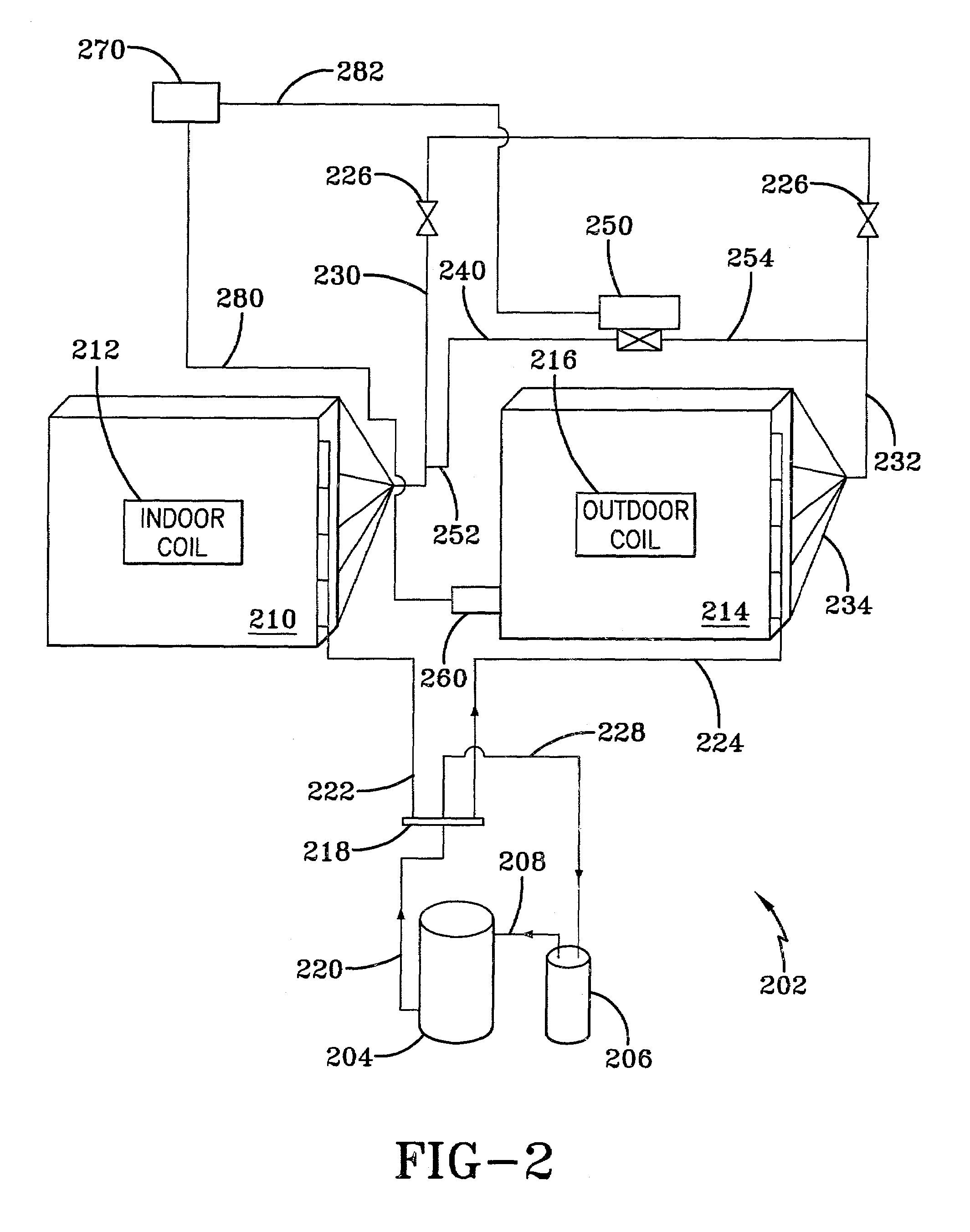
[0031]Referring now to FIG. 4, a slight variation to the previousiy described defrost bypass loop 340 is set forth. This variation results in a different operation of the defrost bypass loop 440. Air-to-air heat pump system 402 is similar to heat pump system shown in FIG. 2. However, in this configuration, temperature sensor 460 is located within outdoor unit 414 to monitor the ambient temperature within outdoor unit 414, but not attached to outdoor coil 416. Alternatively, temperature sensor 460 may be located external to outdoor unit 414 to monitor the ambient temperature. When temperature measuring device 460, transmits a signal to controller 470 indicating that the temperature within outdoor unit 414, or alternatively the outdoor ambient temperature, corresponds to a predetermined set point, controller 470 activates a timing means, such as a timer, for use in a timed sequence operation, which may be preprogrammed into a programmable controller, causing heat pump unit 402 to redu...

example 3

[0032]Referring now to FIG. 5, a different embodiment of the present invention. a slight variation to the previously described defrost bypass loops X40, where X40 represents any of the previously discussed loops, is set forth. This variation results in a different operation of the defrost bypass loop 540. Air-to-air heat pump system 502 is similar to heat pump system shown in FIG. 2. However, in this configuration, a sensor 560 is located either within outdoor coil 516 or within line 524 leaving the evaporator 514, as shown in FIG. 5, or within outdoor coil itself. Sensor 560 monitors a condition of the refrigerant. It can be set to monitor, for example the temperature of the refrigerant or the pressure of the refrigerant gas. For a refrigerant, the temperature at which a phase change from liquid to gas is known. If the temperature of the refrigerant is too low, insufficient refrigerant is undergoing a phase transformation from liquid to gas and the refrigerant gas pressure is also ...


PUM


Abstract

An improvement in defrosting an air-to-air heat pump system when in the heating mode. A bypass loop transfers refrigerant at a higher temperature and pressure than is normally cycled through the outdoor unit to an outdoor coil to defrost ice on the outdoor coil, The bypass loop includes a valve movable between closed and open positions. A sensor monitors a preselected condition indicative of outdoor coil performance. A controller communicates with the valve and the sensor. Once the controller determines that a preselected set point of a preselected condition indicative of deteriorating performance has been reached, based on received sensor signals, the controller sends a signal to open the valve, allowing warm refrigerant to bypass expansion valves and flow to the outdoor unit to defrost the outdoor unit. Once defrosting is accomplished, the valve can be moved to a closed position to resume normal operation of the heat pump unit.

Description

FIELD OF THE INVENTION[0001]The present invention is directed to a defrost mechanism for air-to-air heat pump systems operating in the heating mode for defrosting the outdoor coil of the outdoor unit based on predetermined conditions of the outdoor coil, thereby reducing the need for de-icing electric heating elements or decreasing the amount of time required for defrosting the outdoor coil, or both.BACKGROUND OF THE INVENTION[0002]Air-to-air heat pump systems are heat moving devices used in residential and commercial applications. Heat is absorbed in an evaporator in a first location and released in a condenser in a second location. The systems are designed so that operations can be reversed so that an area can be either cooled or heated. Thus, on reversal of the heat flow direction, the evaporator at the first location becomes a condenser; and the condenser at the second location becomes an evaporator.[0003]During the heating cycle, the outdoor unit acts as an evaporator and the i...

Claims


Application Information

Patent Timeline
IPC IPC(8): G05D23/00F25D21/06F25B13/00F25B47/02
CPCF25B13/00F25B47/022F25B2700/2106F25B2313/0315F25B2600/2501F25B2313/0313
Inventor GAVULA, PATRICK
Owner YORK INT
Why Eureka
Try Eureka