Image displaying projector with a light tunnel and light tunnel structure in an image displaying projector

a technology of image displaying projector and light tunnel, which is applied in the direction of non-linear optics, lighting and heating apparatus, instruments, etc., can solve the problems of increasing the steps of production, increasing the cost, and increasing the risk of glass members deteriorating or breaking, so as to reduce the production cost, improve the radiation of heat, and reduce the number of steps

Inactive Publication Date: 2006-02-28
FUNAI ELECTRIC CO LTD
View PDF9 Cites 24 Cited by
  • Summary
  • Abstract
  • Description
  • Claims
  • Application Information

AI Technical Summary

Benefits of technology

[0015]The tubular portion of the light tunnel according to the present invention is made from a thin metal sheet bent to a tubular form and can thus be fabricated with a fewer number of components and a fewer number of steps, hence decreasing its production cost. Also, the tubular portion made from the thin metal sheet improves the radiation of heat and can thus prevent it from being heated up and fractured by the heat of received light.

Problems solved by technology

The light tunnel in the conventional image displaying projector however has the four glass members bonded by an adhesive to a tubular form thus increasing the steps of production and resulting in the cost up.
Furthermore, as the light tunnel is exposed to the light from the lamp, it is heated up and its glass members which are low in the radiation of heat may deteriorate or fracture.
When the light emitted from the lamp is incident to one end plane of the light tunnel, it enters the glass members and its output from the other end may interrupt the image to be projected.
Accordingly, its arrangement becomes intricate while the action of the angle adjusting is not easy.
Also, the other prior arts disclosed in Japanese Patent Laid-Open Publications HEI8-271854, HEI8-286146, and HEI10-48476 fail to eliminate the foregoing drawbacks.

Method used


Image

  • Image displaying projector with a light tunnel and light tunnel structure in an image displaying projector
  • Image displaying projector with a light tunnel and light tunnel structure in an image displaying projector
  • Image displaying projector with a light tunnel and light tunnel structure in an image displaying projector

Examples


first embodiment

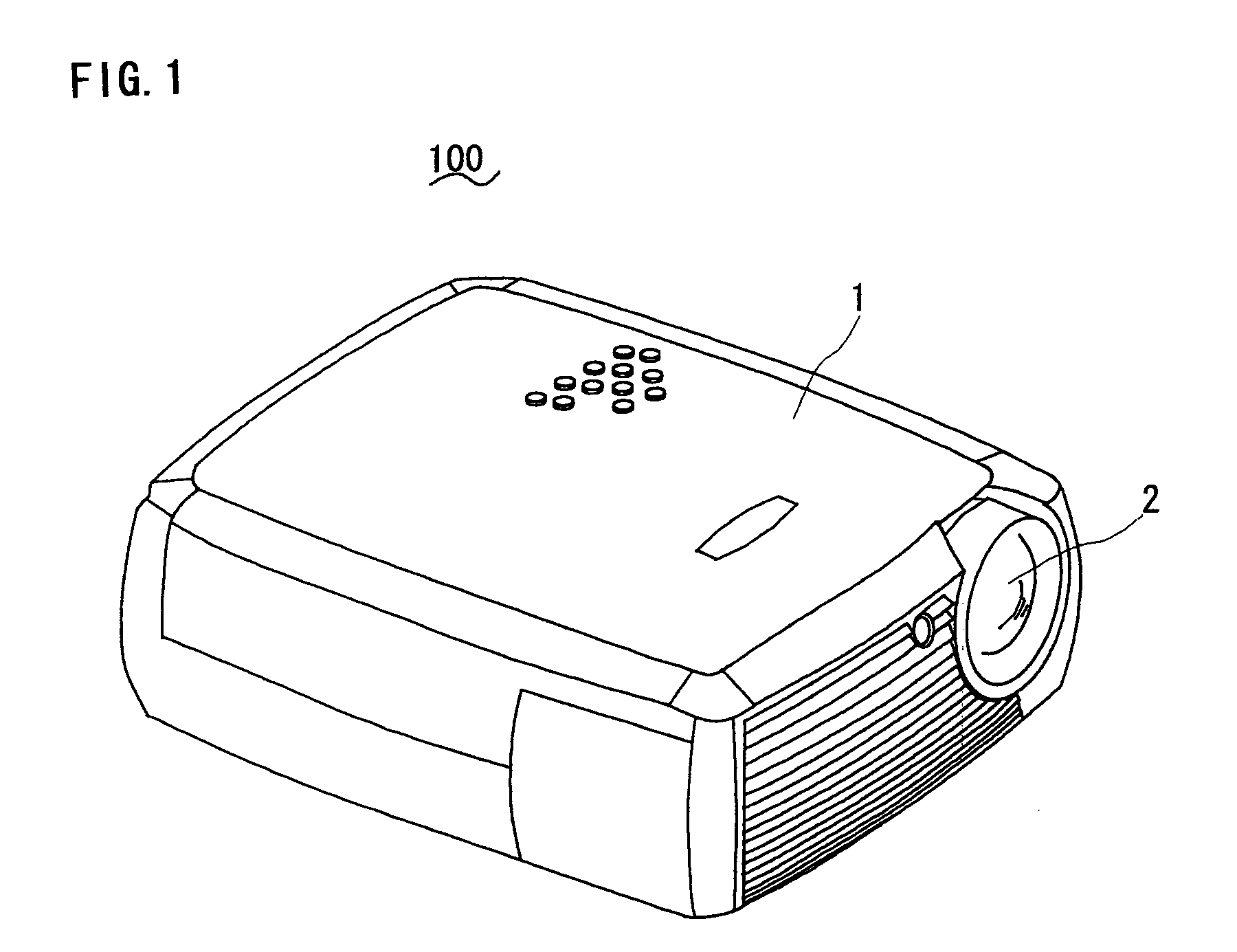
[0029]Some embodiments of the present invention will be described referring to the relevant drawings. The description starts with the present invention. As shown in FIGS. 1 and 2, an image displaying projector 100 is designed for producing an image on an imaging device from an image signal supplied by a personal computer or a video camera and projecting it onto a screen or a wall.

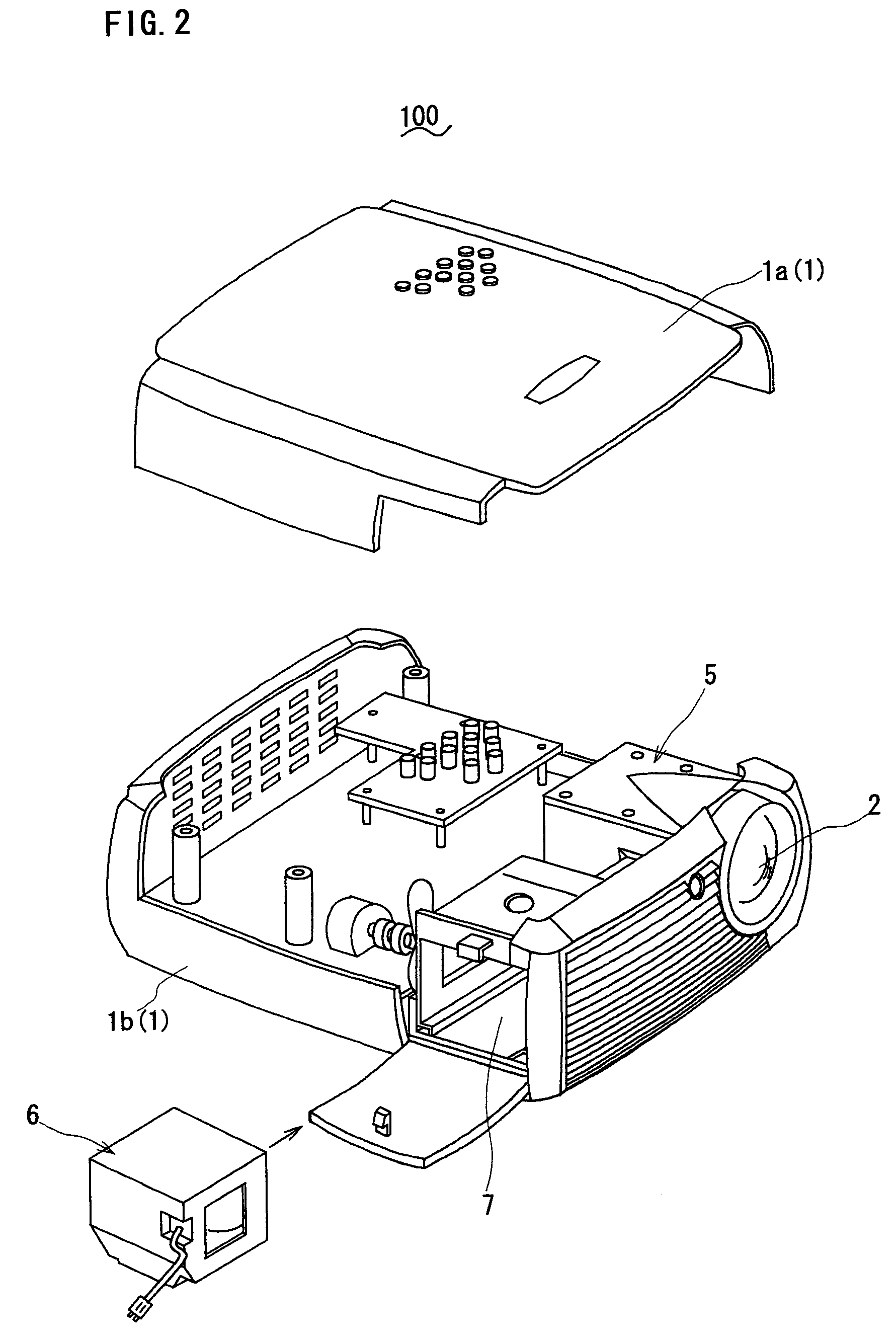
[0030]The image displaying projector 100 has a projection lens 2 provided on the front side of a housing 1 thereof for projecting an optical image produced on the imaging device. Also, the image displaying projector 100 includes an image projection engine 5 for producing an image on the imaging device and projecting it through the projection lens 2 and a lamp unit 6 for illuminating the imaging screen of the image projection engine 5, both accommodated in the housing 1. The housing 1 comprises an upper cover 1a and a lower case 1b. The image projection engine 5 is anchored to the lower case 1b while the lam...

second embodiment

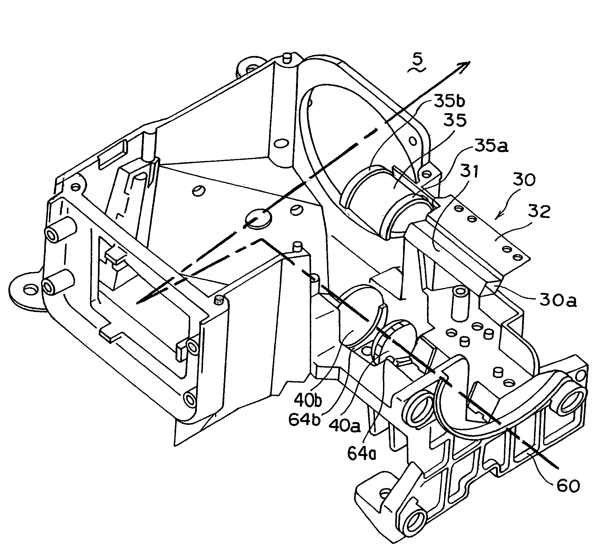
[0042]the present invention will now be described. As shown in FIGS. 5 and 6, a light tunnel 30 of this embodiment has a tubular portion 31, a mounting portion 32, and specifically a lens holder 35 for holding down a couple of lenses 40a and 40b of a tablet lens. The light tunnel 30 is also made of a thin metal sheet and its tubular portion 31 and mounting portion 32 are identical in the configuration to those of the previous embodiment. The lens holder 35 extends continuously to the mounting portion 32 and the tubular portion 31 with elasticity and is shaped by pressing to have a couple of ring-like ends 35a and 35b for engagement with the upper halves of the two lenses 40a and 40b respectively.

[0043]On the other hand, a chassis 60 has a couple of lens holding portions 64a and 64b for holding the lower halves of the two lenses 40a and 40b of the tablet lens. The two lenses 40a and 40b are fitted directly at the lower half with their respective lens holding portions 64a and 64b. The...

third embodiment

[0046]the present invention will be described. Referring to FIG. 7, a light tunnel 30 of this embodiment has a tubular portion 31, input end retainer springs 36a and 36b, output end flexible springs 38a and 38b acting as angle adjusters for mounting the tubular portion 31 to the chassis 60 and adjusting the angle of the tubular portion 31.

[0047]The light tunnel 30 is made of a thin metal sheet and its tubular portion 31 is shaped by the same manner as of the previous embodiment where the thin metal sheet is bent with its reflecting mirror coating inside to have a tubular form. The input end retainer springs 36a and 36b are shaped by folding outwardly an upper tab portion and a lower tab portion at the input opening 30a of the tubular portion 31. In particular, the input end retainer spring 36a has a positioning projection 37a provided thereon and the input end retainer spring 36b also has a positioning projection 37b provided thereon. The output end flexible springs 38a and 38b are ...


PUM

PropertyMeasurementUnit
light wavelengthsaaaaaaaaaa
elasticityaaaaaaaaaa
angleaaaaaaaaaa

Abstract

An image displaying projector is provided comprising a lamp for emitting the light for image projection, a light tunnel for receiving the light from the lamp at one end opening of a tubular portion thereof which has two openings provided at both ends, guiding the light as it reflects on an inner side of the tubular portion, and releasing the light from the other end opening of the tubular portion, and an imaging device for producing an optical image by means of the light released from the light tunnel. The light tunnel is made of a thin metal sheet folded to shape the tubular portion which has two openings provided at both ends. The image displaying projector can easily be manufactured fewer of components and steps. The thin metal sheet prevents the light tunnel from being heated up and fractured by the heat lamp.

Description

BACKGROUND OF THE INVENTION[0001]1. Field of the Invention[0002]The present invention relates to an image displaying projector for projecting an image onto a screen and a light tunnel structure in an image displaying projector.[0003]2. Description of the Related Art[0004]An image displaying projector is known for producing an optical image on its imaging device from its image data supplied by a personal computer or a video camera and projecting it on a screen for display. Such a conventional image displaying projector includes commonly an image projection system shown in FIG. 9 where a light tunnel 92 is provided for condensing and collimating the light received from a lamp 90. In the image projection system, the light emitted from the lamp 90 (its optical axis denoted by the one-dot chain line with the arrow) is colored by a color wheel 91 and then condensed and collimated by the light tunnel 92 before compensated for waveform effects by a corrective lens 93. The light from the lam...

Claims


Application Information

Patent Timeline
Patent Type & Authority Patents(United States)
IPC IPC(8): G03B21/14F21V7/04G02B6/10G02B6/122G02F1/025
CPCG03B21/14G03B21/142G03B21/145
Inventor MORINAGA, KENICHI
Owner FUNAI ELECTRIC CO LTD
Why Eureka
Try Eureka