Tool, tool holder, and machine tool

a tool and tool holder technology, applied in the field of tools, tool holders, and machine tools, can solve the problems of increasing noise from the accelerating apparatus, increasing manufacturing costs, and increasing apparatus size, so as to avoid the effects of heat generation

Inactive Publication Date: 2006-02-28
TOSHIBA MASCH CO LTD
View PDF35 Cites 16 Cited by
  • Summary
  • Abstract
  • Description
  • Claims
  • Application Information

AI Technical Summary

Benefits of technology

[0046]The tool of the seventh aspect of the invention is completely independent from the spindle and any external apparatus, but generates heat when the motor is driven. Therefore, a cooling means is provided at the tool, and part of the electric power generated by the generator is used

Problems solved by technology

Further, at the above super high rotational speed, the noise from the accelerating apparatus can also increase.
Therefore, there is the disadvantage that the manufacturing cost becomes relatively high.
Further, in a case of an accelerating apparatus with a gear mechanism, it is necessary to lubricate the gear or bearing and arrange a supply passage and a discharge passage for the lubricating oil in the accelerat

Method used


Image

  • Tool, tool holder, and machine tool
  • Tool, tool holder, and machine tool
  • Tool, tool holder, and machine tool

Examples


first embodiment

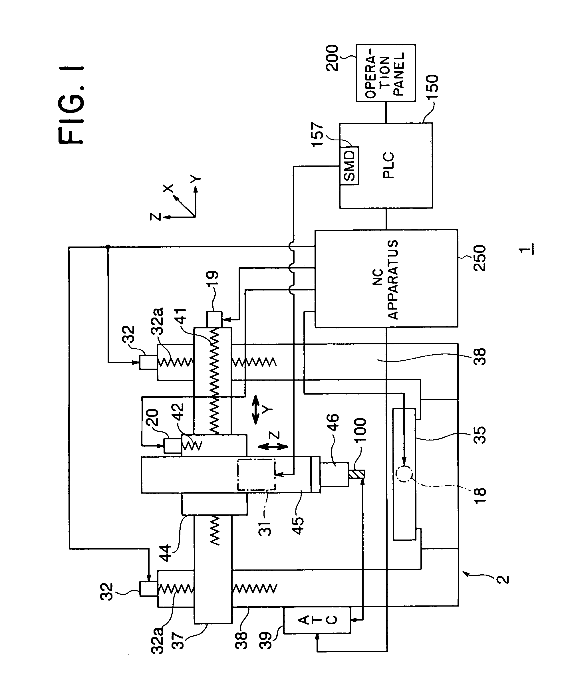
[0066]FIG. 1 is a view of the configuration of a machining center as an example of a machine tool according to the present invention. Note that the machining center is a numerical control machine tool capable of so-called combined machining.

[0067]The machining center 1 is provided with a machine tool body 2, a numerical control apparatus (NC apparatus) 250, and a programmable logic controller (PLC) 150.

[0068]In FIG. 1, the machine tool body 2 is provided with a cross rail 37 having two ends movably supported by shafts of a double housing type column 38. A ram 45 is provided movably in a vertical direction (Z-axis direction) via a saddle 44 supported movably on this cross rail 37.

[0069]The saddle 44 is provided with a not illustrated nut part passing thorough the cross rail 37 in a horizontal direction. A feed shaft 41 with a screw part formed on the outer circumference is screwed into this nut part.

[0070]A servo motor 19 is connected with an end of the feed shaft 41. The feed shaft ...

second embodiment

[0128]The cutting tool 100 of the tool 60 according to the above mentioned embodiment is arranged in the axial center direction of the spindle 46, that is, the shaft of the motor 80 is arranged in the axial center direction of the spindle 46.

[0129]On the other hand, various types of composite machining are required in the machining center 1. With just a tool 60 with the cutting tool 100 oriented in the axial center direction of the spindle 46, composite machining cannot be handled.

[0130]In the present embodiment, an explanation will be made of a tool able to handle composite machining of a machining center 1.

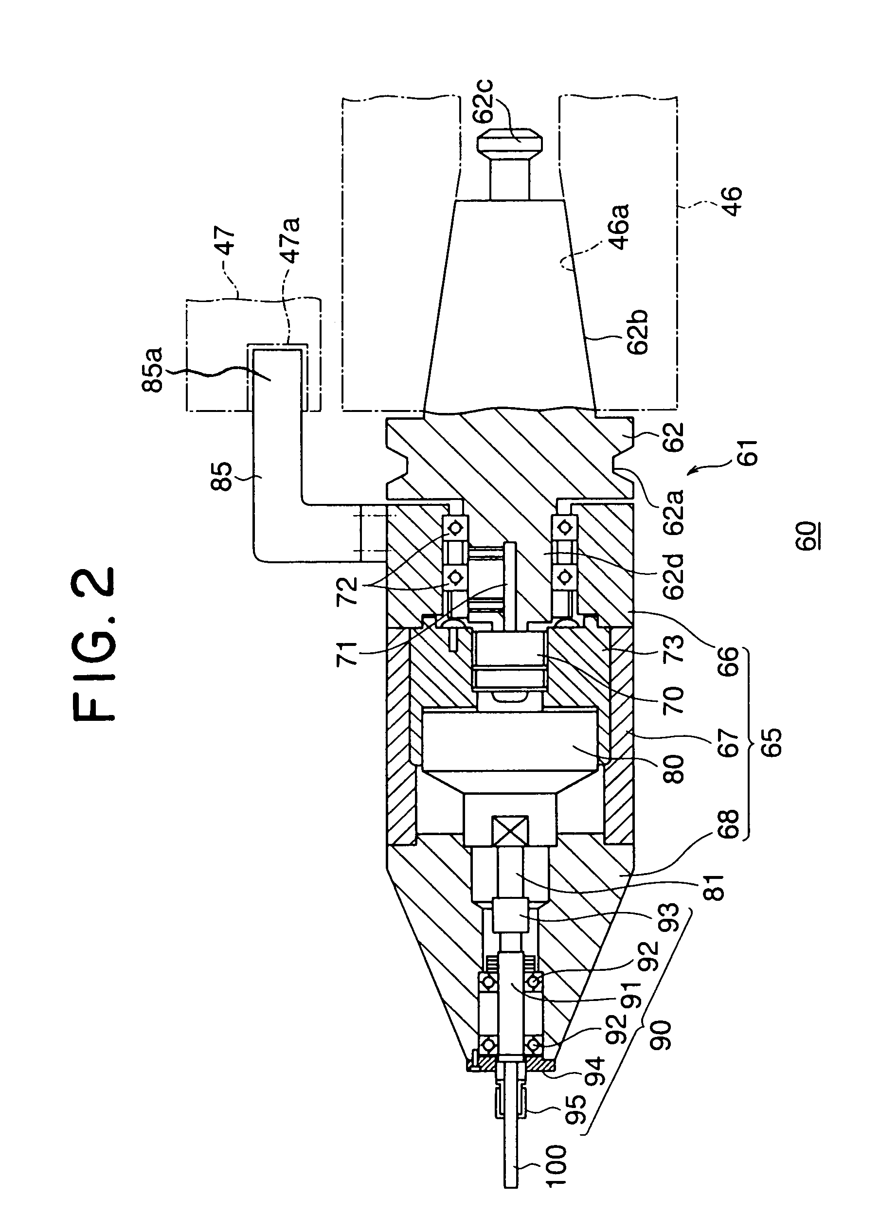
[0131]FIG. 4 to FIG. 6 are schematic views of the configuration of tools according to another embodiment of the present invention. Note that FIG. 4 and FIG. 6 use the same reference numerals for parts the same as in the above first embodiment. Further, the tools shown in FIG. 4 to FIG. 6 are basically the same in operation as the tool 60 according to the above first embodiment.

[...

third embodiment

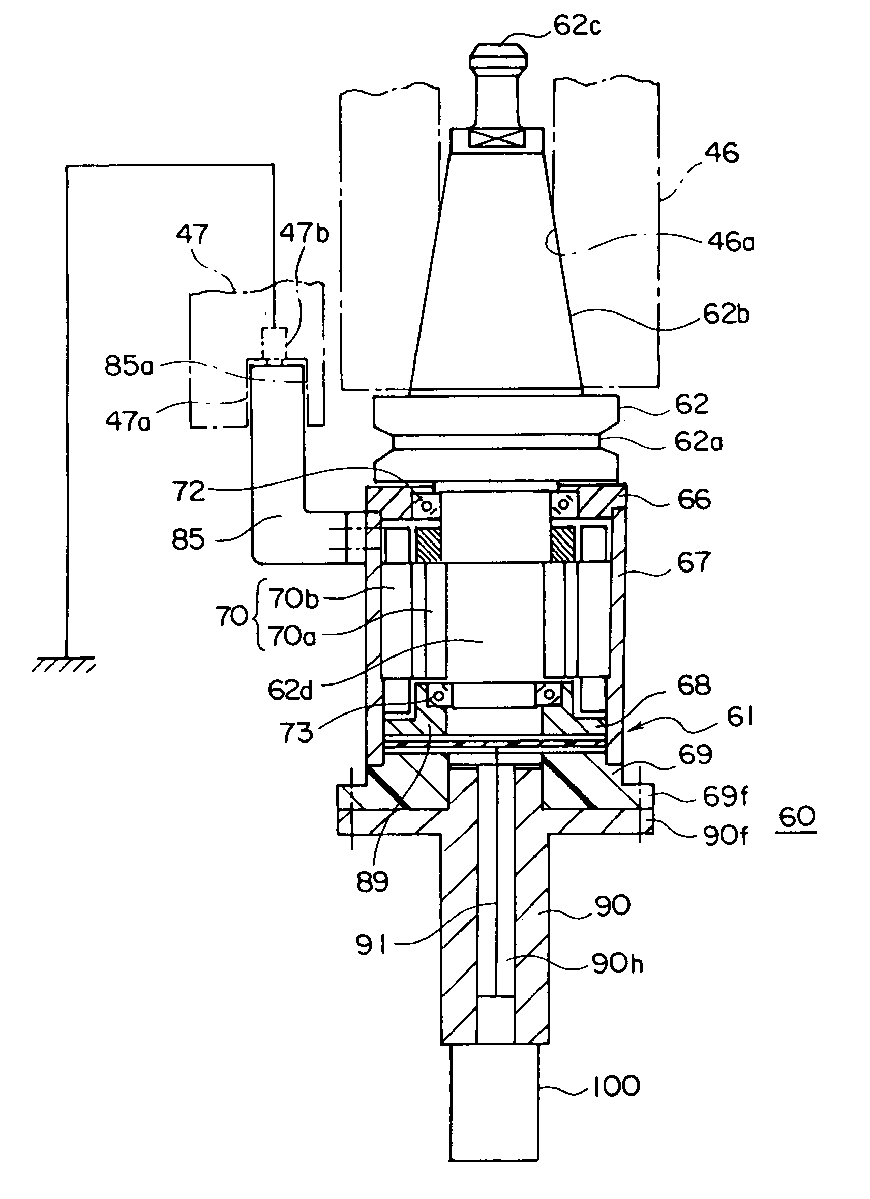
[0150]FIG. 7 is a sectional view of the configuration of an electrodischarge machining tool according to a third embodiment of the present invention.

[0151]In FIG. 7, the electrodischarge machining tool 60 is comprised of an electrode 100 and a holder 61 holding this electrode 100. Note that the electrodischarge machining tool 60 according to the present embodiment may be attached to a spindle 46 by an automatic tool changer 39 in the same way as the above ordinary tool T.

[0152]The holder 61 is provided with an attachment part 62, bearing holding part 66, casing 67, bearing holding part 68, locking part 85, insulating part 69, electrode holding part 90, circuit board 89, and generator 70.

[0153]The attachment part 62 is provided with a grip 62a, a taper shank 62b to be attached to a taper sleeve 46a formed at the front end of the above spindle 46, a pull stud 62c formed at the front end of this taper shank 62b, and a shaft 62d rotatably held by the bearing holding parts 66 and 68 thro...


PUM

PropertyMeasurementUnit
Currentaaaaaaaaaa

Abstract

A tool attachable to a spindle of a machine tool by an automatic tool changer in the same way as an ordinary tool, capable of being driven without connecting with an external power supply etc., and able to rotate at a rotational speed different from than that of the spindle of the machine tool without supply of electric power from the outside, provided with a machining tool for machining a workpiece, a motor connected with the machining tool and rotating the machining tool, and a generator to which rotary force is transmitted from the spindle of the machine tool and generating electric power to drive the motor, the shaft of the motor being arranged in an orientation different from the axial center of the spindle.

Description

[0001]This is a Continuation Application of U.S. application Ser. No. 10 / 270,248, filed Oct. 15, 2002, now U.S. Pat. No. 6,752,750 which is based upon and claims the benefit of priority from the prior Japanese Patent Application Nos. 2001-317165, filed Oct. 15, 2001, 2001-365902, filed Nov. 30, 2001, 2001-367404, filed Nov. 30, 2001, and 2001-367428, filed Nov. 30, 2001.BACKGROUND OF THE INVENTION[0002]1. Field of the Invention[0003]The present invention relates to a tool to be attached to a spindle of a machine tool for machining a workpiece.[0004]2. Description of the Related Art[0005]In for, example, a machining center or other machine tool provided with a spindle, the maximum rotational speed of the spindle (per unit time) is determined by the structure of a main bearing rotatably supporting the spindle and a lubrication system. For this reason, when rotation of a tool at a higher rotational speed than the maximum rotational speed of the spindle is desired, an accelerating appar...

Claims


Application Information

Patent Timeline
IPC IPC(8): B23H7/26B23Q5/04B23Q15/00B23Q5/10
CPCB23Q5/043B23Q5/045B23Q5/10Y10T408/65Y10T409/309352Y10T409/30448Y10T409/309296Y10T409/30952Y10T483/1736B23Q15/00
Inventor ADACHI, SAKASHIKATSUMATA, KOJI
Owner TOSHIBA MASCH CO LTD
Why Eureka
Try Eureka