

Motor control apparatus having current supply phase correction
a technology of motor control and phase correction, which is applied in the direction of motor/generator/converter stoppers, peptides, dc motor stoppers, etc., can solve the problems of reducing the accuracy of stop position, rotors cannot be driven normally or are rendered out of control, and the shift position of an automatic transmission of a vehicle may be determined erroneously, so as to increase the rotor rotation speed and the effect of preventing overshooting
- Summary
- Abstract
- Description
- Claims
- Application Information
AI Technical Summary
Benefits of technology
Problems solved by technology
Method used
Image

Examples
first embodiment
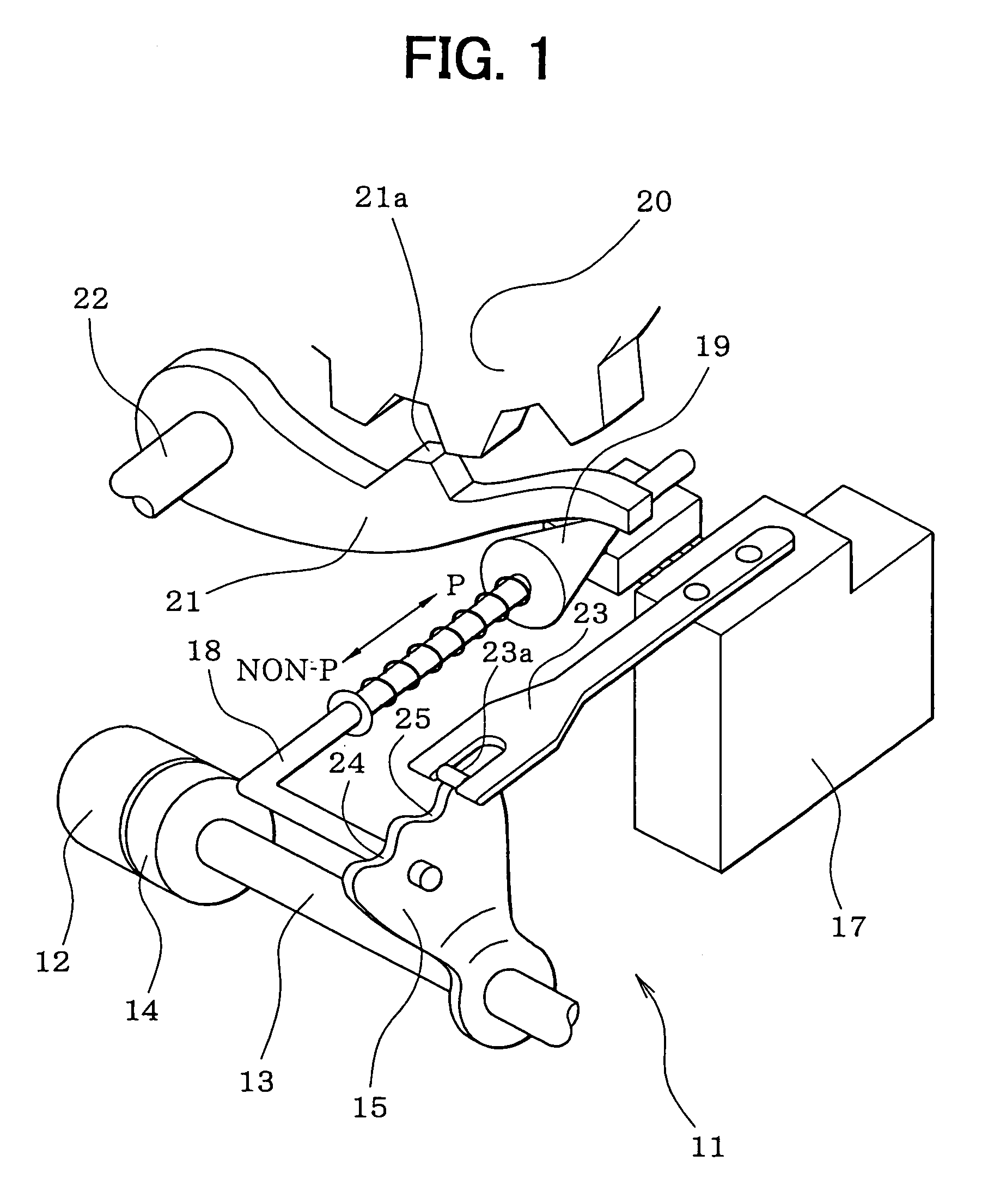
[0048]A first embodiment in which the present invention is applied to a position switching device of an automatic transmission of a vehicle will be described in detail.
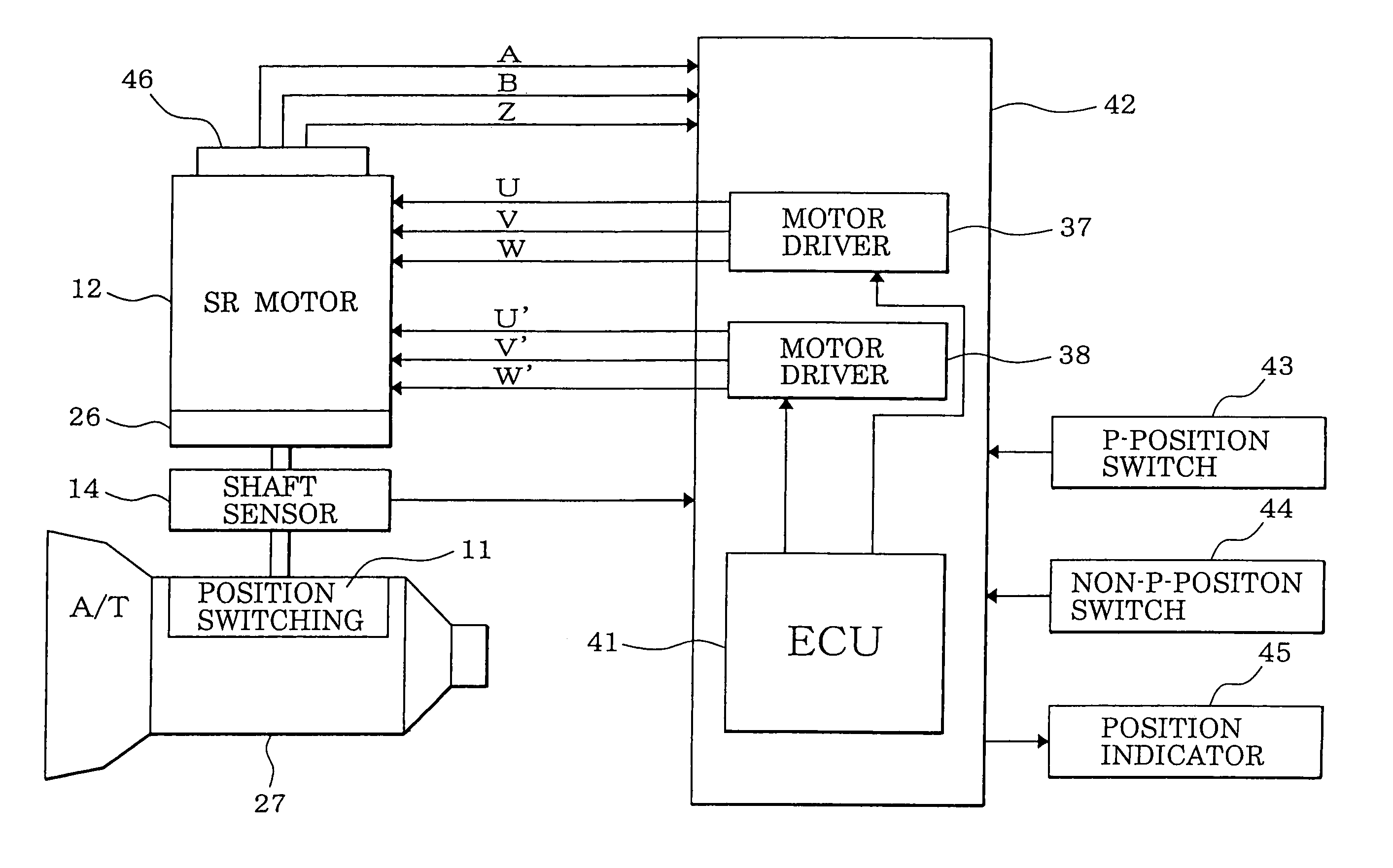
[0049]Referring first to FIG. 1, a position switching mechanism 11 is indicated with numeral 11. A motor 12 as a drive source of the position switching mechanism 11 is a switched reluctance motor, for example, incorporates a speed reducing mechanism 26 (FIG. 4), and is equipped with an output shaft sensor 14 for detecting a rotation position of an output shaft 13 of the speed reducing mechanism 26. A detent lever 15 is fixed to the output shaft 13.
[0050]An L-shaped parking rod 18 is fixed to the detent lever 15. A conical body 19 that is provided at the tip of the parking rod 18 is in contact with a lock lever 21. The lock lever 21 is moved in the vertical direction in accordance with the position of the conical body 19 and thereby locks or unlocks a parking gear 20. The parking gear 20 is attached to the output shaft...
second embodiment
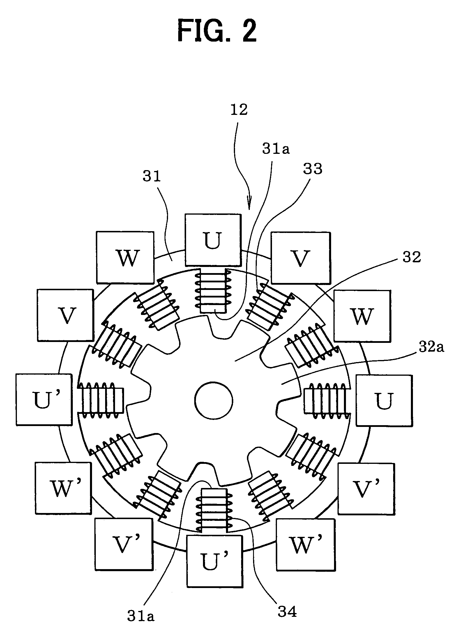
[0166]In the first embodiment, the rotation amount (of the rotor 32 (i.e., the rotor rotation angle) is converted into the manipulated variable of the position switching mechanism 11 (i.e., the slide length of the parking rod 18) via the rotation transmission system consisting of the speed reducing mechanism 26, the output shaft 13, the detent lever 15, etc. Play exists between the parts constituting the rotation transmission system. For example, backlash exists between the gears of the speed reducing mechanism 26. In a structure in which a connecting portion having a non-circular cross-section that is formed at the tip of the rotary shaft of the motor 12 is fitted into a fitting hole of the output shaft 13, a certain clearance is needed to facilitate the work of fitting the former into the latter.
[0167]Further, as shown in FIG. 27, when the engaging portion 23a of the detent spring 23 moves into the P-position holding recess 24 or the non-P-position holding recess 25 of the detent ...
third embodiment
[0212]Next, a motor control according to a third embodiment of the invention will be described by using routines shown in FIGS. 33–35.
[0213]A motor control routine shown in FIG. 33 is executed in a prescribed cycle during an ignition switch on period. Upon activation of this routine, it is determined at step 3601 whether a feedback control execution condition is satisfied. The feedback control execution condition is satisfied if, for example, both of the following conditions (1) and (2) are met:[0214](1) an initial drive has finished (i.e., learning of an initial positional deviation learned value Gcnt has finished.[0215](2) no system failure or abnormality in output pulses of the encoder 46 (e.g., noise, loss of a pulse, a signal line disconnection) is detected.
[0216]If both of the two conditions (1) and (2) are met, the feedback control execution condition is satisfied and the routine proceeds to step 3602, where a feedback control is performed. In the feedback cont...
PUM
| Property | Measurement | Unit |
|---|---|---|
| rotation angle | aaaaa | aaaaa |
| rotation angle | aaaaa | aaaaa |
| electrical angle | aaaaa | aaaaa |
Abstract
Description
Claims
Application Information