
Electronic stethoscope

Inactive Publication Date: 2006-02-28
3M INNOVATIVE PROPERTIES CO
View PDF19 Cites 32 Cited by
  • Summary
  • Abstract
  • Description
  • Claims
  • Application Information

AI Technical Summary

Benefits of technology

[0013]With the access to modern technology it is obvious that digital filtering will be used, because it permits reprogramming without lengthy calibration. This also opens possibilities for letting the electronic stethoscope store filter transfer functions which correspond to the known main types of stethoscopes (small and large cup, with or without membrane) in order that the physician using it has only to select the filter function which corresponds best to the type of stethoscope at this particular physician has the best training in—or which according to traditional teaching is found as best suited to the task. In this respect it will also be feasible to let digital signal processing adapt the filter to the signal whereby a real improvement in the signal-to-noise ratio is obtained.
[0022]Such an improvement in the reproducibility is a prerequisite for obtaining a meaningful result when storing a sound which has been determined during an examination, in order to compare it to a corresponding sound determined later. This sound may be repeated cyclically according to requirements so that weakly represented characteristics may be more easily identified. A series of such sounds may be stored electronically with a view to A / B comparisons. It is quite feasible to store a patient's individual, established sound on a medium which is attached to the file and which may be replayed at a later examination in order that a concrete comparison may be performed and hence a much more precise evaluation of a development, even though several independent physicians might perform the examinations. This sound may equally be stored in the stethoscope itself and may be recalled by entering a code. It would be most relevant to store the unfiltered sound which during comparison is subjected to the same filtering as the direct sound in the stethoscope according to the basic principle of the invention. Correspondingly, it may be expedient to let the stethoscope contain a store for a number of standard sounds which may be recalled for the identification and / or characterization of a new sound.

Problems solved by technology

However, its value and / or performance to the users have fallen, due to the technical development of society.
The increased machine noise, in particular in hospitals, in practice, causes the signals to lie below, or at the most at, the lower limit of human hearing.
To this may be added that more and more young persons suffer from hearing loss at the time they may embark on a medical education, and hence the acoustic stethoscope has in practice reached its limit of performance.
It has long been realized that a traditional acoustic stethoscope introduces many linear distortions in its signal transmission, in particular because of the possibility for standing waves in the long tubes.
However, the physician's reliability in using stethoscopes is generally so large, in particular when using the stethoscope they have become used to, that the impulse response problem has not been regarded as a bar to the use of acoustic stethoscopes.
For this reason, it has not been attractive to use an electronic stethoscope, even though it gives the possibility of active amplification to any desired degree.
The ability to distinguish phenomena which has laboriously been learnt by the physician does not help any longer.
However, such a stethoscope is complex, prone to failure, and expensive to produce.
Furthermore, the feedback microphone wold be prone to performance degradation (e.g., change in frequency response, sensitivity, etc.) over time from either natural aging, exposure to harsh environments and / or abuse by the user.
Such performance degradation of the microphone would, in turn, degrade the performance of the device.
However, neither of these known attempts provide realism to the heart sound, and the sounds produced are so different from the sounds that physicians have been trained to recognize that improved signal processing is necessary to make realistic use of binaural ausculation.
However, to date, no known attempt has been made to use this ability in an electronic stethoscope to separate or transform defined sound components so as to present different features to each of the physician's ears.

Method used


Image

  • Electronic stethoscope
  • Electronic stethoscope
  • Electronic stethoscope

Examples


example

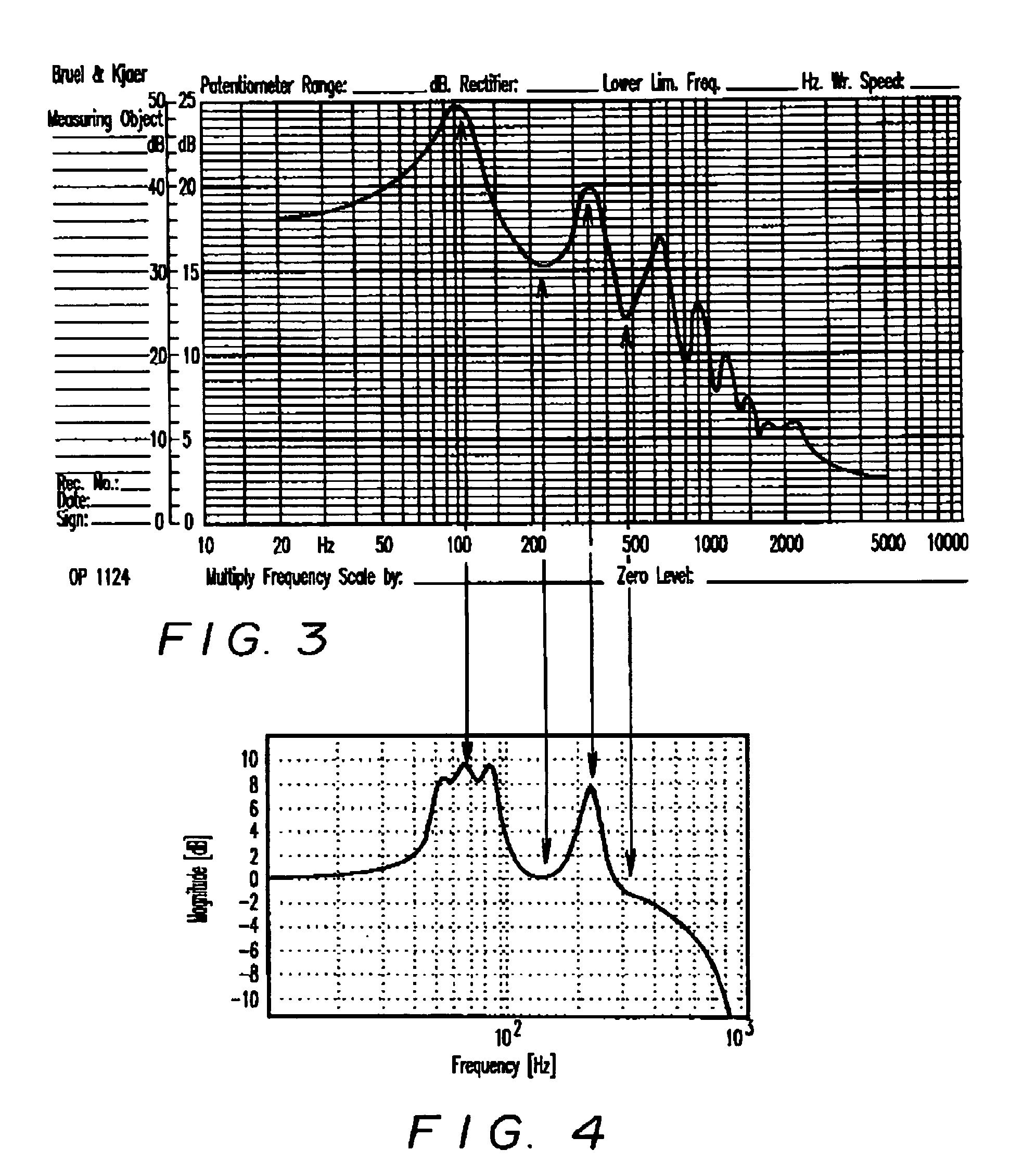
[0038]A Littman Classic II stethoscope was measured by two methods. On the one hand, the mechanical dimensions were measured, and the electroacoustic equivalent circuit was developed in the situation where the stethoscope was in contact with the skin as the transmitter and the ear pieces inserted in the ear canal. On the other hand, a unit was measured in a standard Brüel & Kjær acoustic measuring setup with a sweep oscillator and filter and a plotter. FIG. 3 shows the measured transfer function. On the basis of a calculation of the transfer function by means of the electroacoustic equivalent, the filter coefficients for a digital filter were calculated according to standard practice for the first resonance peaks in the transfer function. These coefficients are reproduced in Table 1.

[0039]

TABLE 1Filter coefficients for electronic stethoscope (digital filter)First resonator (2nd order IIR filter)A0 =  0.167283222079277039A1 =−0.331625401973724365A2 =  0.164647430181503296B0 =  1.0000...


PUM


Abstract

An electronic stethoscope having a vibration transducer, an amplifier, a headphone arrangement, and at least one digital filter for establishing at least one impulse transfer function corresponding to at least one acoustic stethoscope type. Thus, the signals heard will correspond to those learned, and thereby the advantages of greater amplification and elimination of noise sources may be fully utilized. The ability to compensate for an individual doctor's hearing loss is enabled. Furthermore, with stereoscopic embodiments, sound frequency distributions can be transformed to spatial or temporal sound distributions perceivable by the user facilitating, for example, the detection of heart murmurs and the taking of blood pressure.

Description

CROSS REFERENCE TO RELATED APPLICATION[0001]This application is a continuation-in-part of co-pending U.S. patent application Ser. No. 08 / 793,622.BACKGROUND OF THE INVENTION[0002]1. Field of the Invention[0003]The invention relates to an electronic stethoscope of the type comprising a vibration transducer, an amplifier, and a headphone arrangement.[0004]2. Description of Related Art[0005]Stethoscopes are used by physicians to listen to sounds from the organism, in particular heart and lungs. The phenomena listened for emit sounds with frequencies from below 16 Hz to about 8 kHz, but a serious low pass filtering occurs during the passage of tissue and skin. The skin acts like a transmitter of those signals which are subsequently accessible. The construction of the stethoscope ascertains that only a small area of the skin is listened to at a time, and that sounds in the room outside are dampened, and thus, the signal-to-noise ratio is somewhat improved. Physicians train actively in the...

Claims


Application Information

Patent Timeline
IPC IPC(8): A61B7/04
CPCA61B7/04A61B7/045
Inventor BAEKGAARD, KNUD ERIKDALGAARD, TORBEN NAURBO
Owner 3M INNOVATIVE PROPERTIES CO
Learn More