
Method and apparatus for imaging using continuous non-raster patterns

Inactive Publication Date: 2006-03-07
BOARD OF RGT NEVADA SYST OF HIGHER EDUCATION ON BEHALF OF THE UNIV OF NEVADA RENO
View PDF5 Cites 29 Cited by
  • Summary
  • Abstract
  • Description
  • Claims
  • Application Information

AI Technical Summary

Benefits of technology

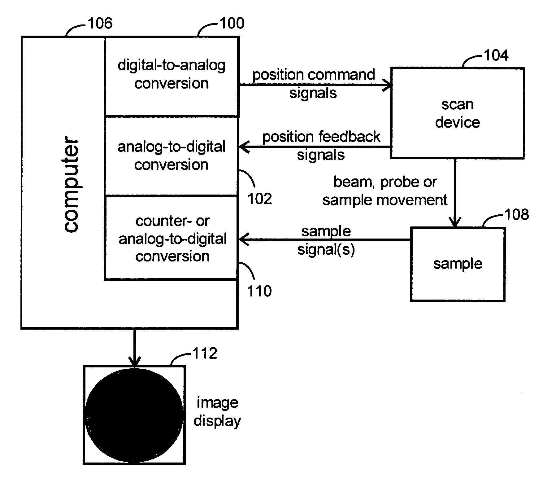
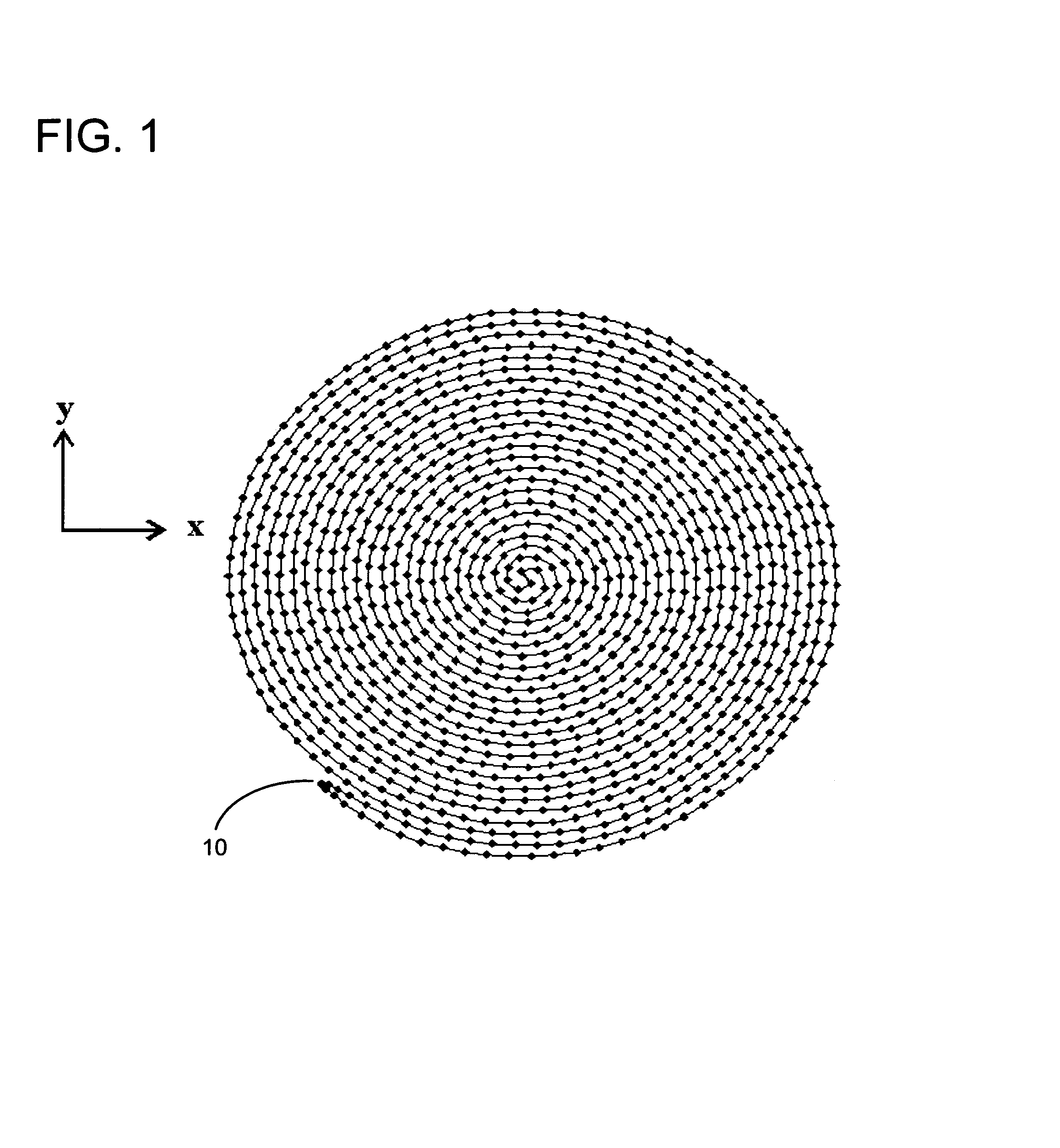
[0009]The present invention utilizes non-raster scanning patterns to perform rapid probe steering and data collection within imaging devices such as scanning microscopes or beam projection systems such as those used to perform maskless lithography. By using waveforms to direct probe-steering devices in each spatial dimension that are primarily sinusoidal in nature, continuous spiral scanning patterns are generated with a number of advantages. An object of the present invention is to optimize the rate of scanning and / or data collection by increasing the number of data points and / or the number of frames projected or acquired per unit time. In confocal microscopy applications, these high scan rates can be attained without sacrificing the ability to achieve diffraction-limited spatial resolution. The present invention also produces smooth movements to maximize performance and reduce wear and tear on electromechanical scanning devices. The present invention also allows for software-controlled location (i.e. panning), magnification (i.e. zoom), spatial resolution and temporal resolution. By using software algorithms and position feedback signals to determine probe location and orientation, the present invention also optimizes the spatial accuracy of the assignment of pixel locations. The present invention also allows the user to select from a continuous scale between temporal versus spatial resolutions. The present invention also facilitates automated, intelligent probe-steering control in a repeated fashion since the start and end points of each scan are near the same location.
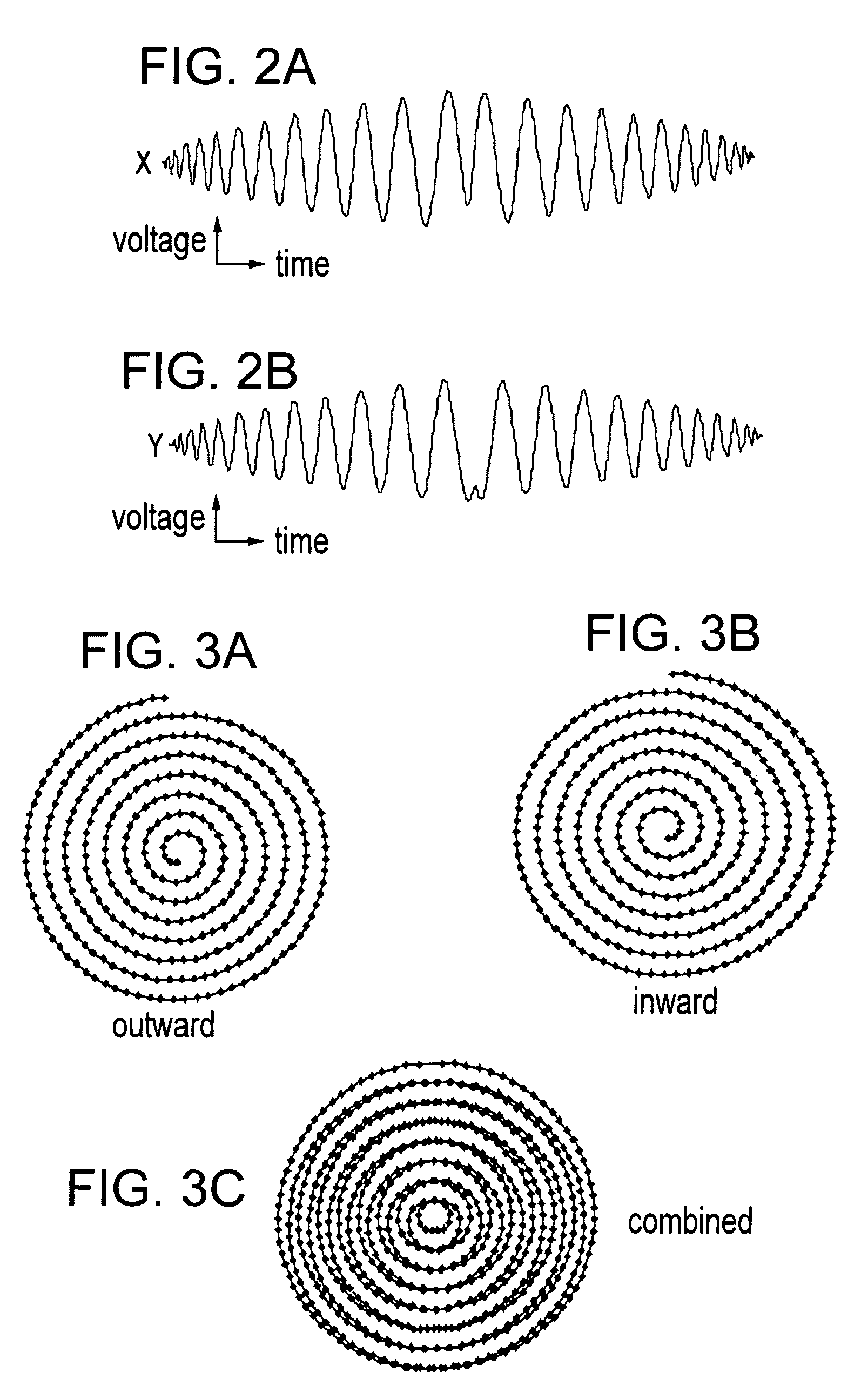
[0010]In an embodiment of the present invention, the scanning pattern utilizes an Archimedes' spiral that begins at a central location and spirals out to a desired radius. The beam direction is then turned around and the spiral is connected in a continuous fashion to a second Archimedes' spiral that spirals inward, filling the gap approximately midway between lines generated by the first spiral. The pattern terminates at the central location where the process can be repeated without interruption in the gathering of data. In an alternative embodiment, the scanning pattern utilizes an Archimedes' spiral that spirals out to a specified radius. The pattern then, without changing direction, continuously spirals inward to the center where the sequence can be re-initiated. For maximum temporal resolution during imaging, data gathered during the outward and inward spirals can be used to generate separate frames or images. The outcome is a class of spiral scanning patterns that minimize accelerations needed to produce scanned images and generate serial data streams in which little or no time is lost projecting to, or collecting from, unwanted regions. In embodiments, the present invention can incorporate substantially rectangular spiral patterns, where portions of the spiral pattern are distorted to provide a larger useable area than a round spiral pattern.

Problems solved by technology

However, the system is not designed for gathering images at high frame rates and, in general, any system that moves an object solely by moving a stage results in scanning that is considerably slower than one that involves steering a beam.

Method used


Image

  • Method and apparatus for imaging using continuous non-raster patterns
  • Method and apparatus for imaging using continuous non-raster patterns
  • Method and apparatus for imaging using continuous non-raster patterns

Examples


Embodiment Construction

[0027]The primary factor that limits the rate at which beam-steering devices can operate is the amount of force required to generate movement. Movement can be computed from a=f / m, where f is the applied force, m is the mass of the moving object (e.g. mirror and any attachment components) and a is acceleration (second time derivative of displacement). Force can be generated by electrical energy to produce displacement in electromechanical devices such as galvanometers. A maximal rate of movement arises because of limitations in the ability to both generate and dissipate electrical power within the small volumes occupied by such beam-steering devices. If attempts are made to expand the size of beam-steering devices, additional limits on the mass or complexity of linkages between the force generating device and the mirror assembly at high displacement rates are imposed due to friction and inertia. In order to keep peak forces low, accelerations (in each dimension, including angular acc...


PUM


Abstract

A method and apparatus for performing data collection within a device is disclosed. A device steers a scanning probe in a continuous, non-raster pattern across a specimen. The specimen is supported by a stage, and data is collected in response to interaction between the probe and the specimen to form a data set. Spiral scanning patterns without turnaround regions are utilized in embodiments of the present invention, both with and without rounded corners in the scanning patterns.

Description

RELATED APPLICATION[0001]This application claims priority to U.S. provisional patent application Ser. No. 60 / 452694, filed Mar. 6, 2003 with the United States Patent and Trademark Office, which is co-pending.FIELD OF THE INVENTION[0002]This invention relates to the field of scanning microscopy where a specimen is scanned using non-raster, continuous-spiral patterns with particular applications in laser scanning confocal microscope systems as well as beam projection systems.BACKGROUND OF THE INVENTION[0003]In optical scanning microscopy, a specimen is scanned with a probe by moving a specimen relative to a stationary beam or by moving a beam relative to a stationary specimen. Alternatively, a spinning disk containing an array of apertures can be placed between the light source and the specimen so that regions of the specimen are illuminated in a patterned and sequential manner. One objective of laser scanning confocal microscopy is to realize diffraction limited spatial resolution th...

Claims


Application Information

Patent Timeline
IPC IPC(8): H01J3/14G01Q60/24G02B21/00
CPCB82Y35/00G03F7/704G02B21/0024G01Q10/06B82Y20/00G02B21/0036
Inventor PUBLICOVER, NELSON GEORGESUTKO, JOHN LEONARD
Owner BOARD OF RGT NEVADA SYST OF HIGHER EDUCATION ON BEHALF OF THE UNIV OF NEVADA RENO
Learn More