Ultrasonic vibration apparatus use as a sensor having a piezoelectric element mounted in a cylindrical casing and grooves filled with flexible filler

a technology of piezoelectric elements and ultrasonic vibration, which is applied in the direction of mechanical vibration separation, piezoelectric/electrostrictive device details, device material selection, etc., can solve the problems of narrow directivity not being obtained, and little advantage in obtaining narrow directivity

Inactive Publication Date: 2006-03-07
MURATA MFG CO LTD
View PDF38 Cites 21 Cited by
  • Summary
  • Abstract
  • Description
  • Claims
  • Application Information

AI Technical Summary

Benefits of technology

[0011]Accordingly, objects of this invention are to provide a miniaturized ultrasonic vibration a

Problems solved by technology

However, when the apparatus is used as an ultrasonic sensor, because of restriction in the size in the outer diameter and restriction of the wavelength to be used, the narrow directivity cannot be obtained without causing the apparatus to be large or

Method used


Image

  • Ultrasonic vibration apparatus use as a sensor having a piezoelectric element mounted in a cylindrical casing and grooves filled with flexible filler
  • Ultrasonic vibration apparatus use as a sensor having a piezoelectric element mounted in a cylindrical casing and grooves filled with flexible filler
  • Ultrasonic vibration apparatus use as a sensor having a piezoelectric element mounted in a cylindrical casing and grooves filled with flexible filler

Examples


first embodiment

[0030]The construction of an ultrasonic vibration apparatus as an ultrasonic sensor according to this invention is described with reference to FIGS. 1 to 4.

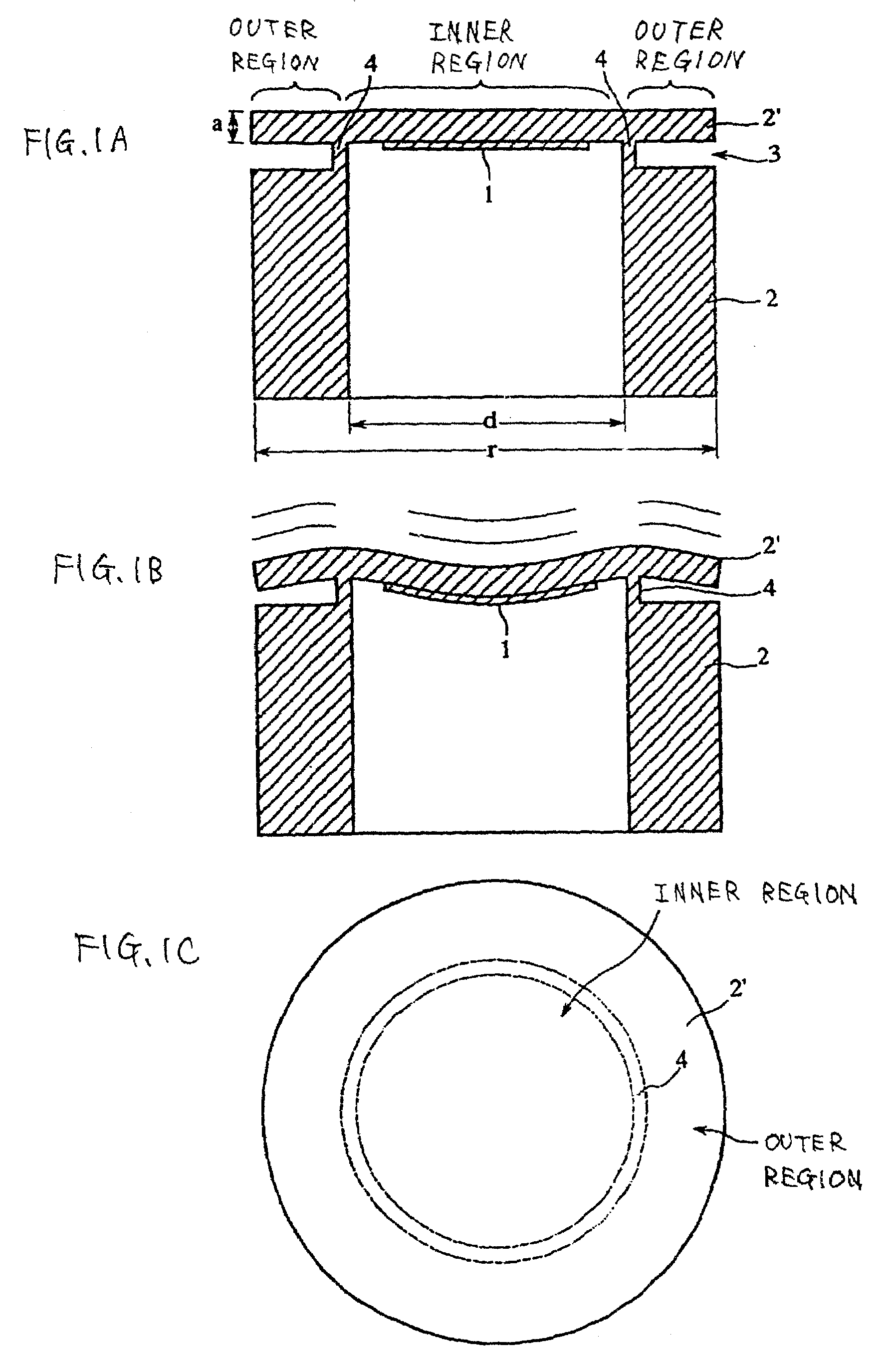
[0031]FIGS. 1A, 1B, and 1c are cross sectional and top plan views showing the construction of the ultrasonic vibration apparatus. As shown in FIG. 1A, a casing 2 forms a cylindrical shape having one end thereof closed and is molded by die casting or cutting of aluminum. The closed end of this casing 2 is formed in which, by providing a groove 3 in the outer surface of the casing which is in proximity to the closed end, the thickness in the emitting direction of the outer peripheral surface of the casing which is in proximity to the closed end is reduced, thereby this closed overall end constitutes the disk-like vibration plate 2′. At the same time, the above part having the thickness thereof reduced constitutes a supporting unit 4 for supporting the disk-like vibration plate 2′.

[0032]As shown in FIG. 1C, in the above supporting u...

second embodiment

[0040]Accordingly, the construction of an ultrasonic vibration apparatus which solves the foregoing problem is described with reference to FIGS. 5 to 8.

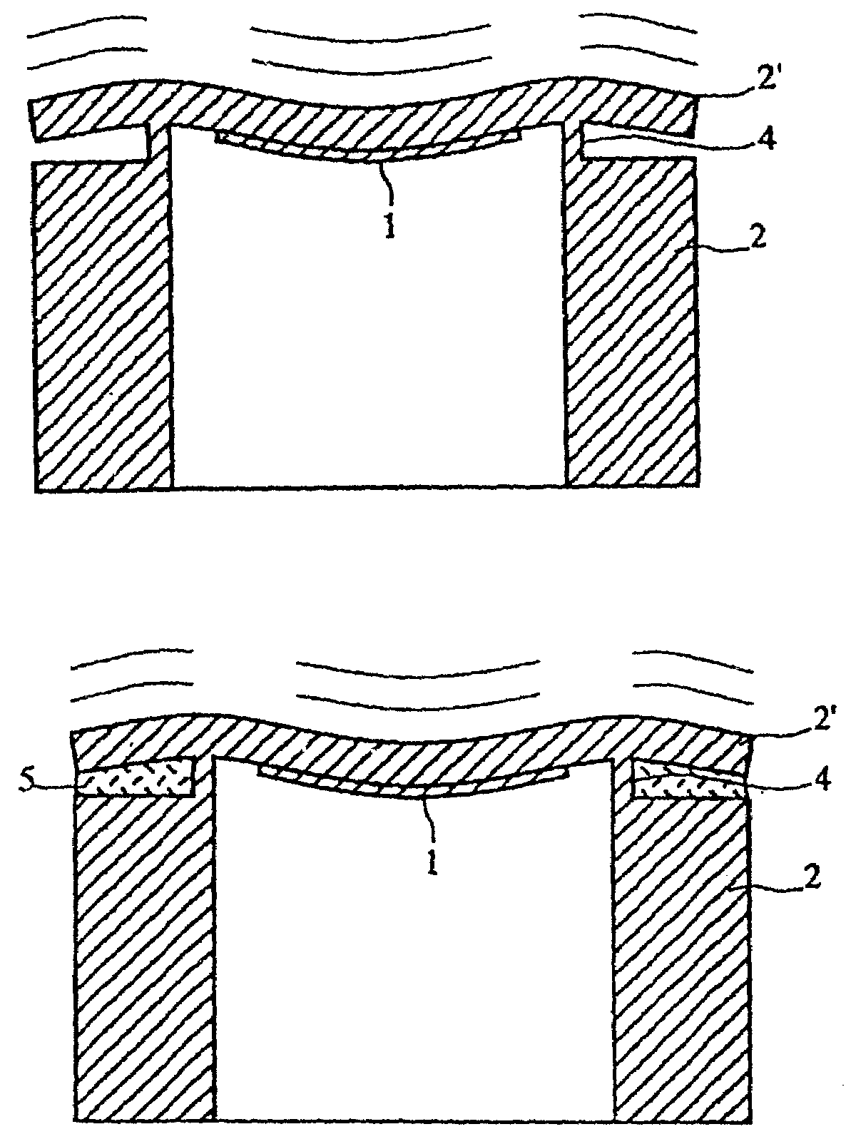
[0041]FIGS. 5A to 5C are cross sectional and top plan views showing the construction of the ultrasonic vibration apparatus. It differs from the ultrasonic vibration apparatus shown in FIGS. 1A to 1C in that filler 5 is filled in the groove 3. As this filler 5, flexible filling material having a hardness lower than that of the casing 2 is used.

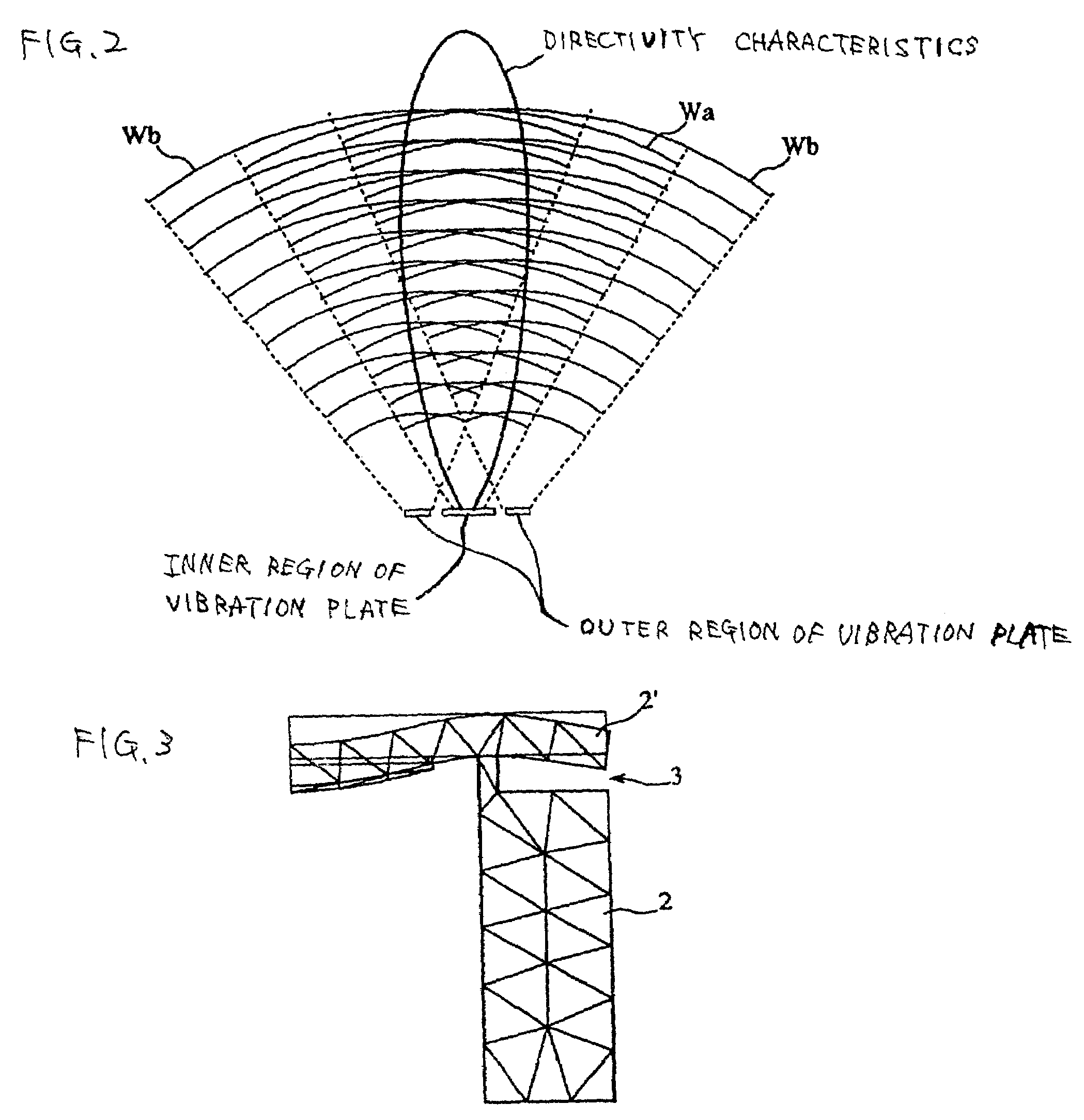
[0042]FIG. 5B shows a state in which the disk-like vibration plate 2′ is deformed when vibrating due to piezoelectric vibration of the piezoelectric element 1. As a consequence of the bending vibration of the piezoelectric element 1, the disk-like vibration plate 2′ bending-vibrates in which the supporting unit 4 thereof serves as a node of vibration and in which the central part of the inner region and the outer peripheral portion of the outer region serve as antinodes of vibration. At this ti...


PUM


Abstract

An ultrasonic vibration apparatus includes a casing having a vibration face, a piezoelectric element mounted in the casing, and a disk-like vibration plate supported at a position along a concentric circle differentiating two regions, an inner region and an outer region. In the ultrasonic vibration apparatus, the disk-like vibration plate is constructed so as to be a part of the casing serving as the vibration face, and, the piezoelectric element is mounted in the central part of the disk-like vibration plate, thereby causing the inner region and the outer region to vibrate in substantially the same phase.

Description

BACKGROUND OF THE INVENTION[0001]1. Field of the Invention[0002]The present invention relates to an ultrasonic vibration apparatus such as an ultrasonic sensor used for detecting an object by transmitting and receiving ultrasonic waves.[0003]2. Description of the Related Art[0004]Hitherto, as disclosed in, for example, Japanese Unexamined Patent Application Publication No. 8-15416, Japanese Unexamined Patent Application Publication No. 8-237795, Japanese Unexamined Patent Application Publication No. 9-284896, and Japanese Unexamined Patent Application Publication No. 10-257595, ultrasonic vibration apparatuses such as ultrasonic sensors employ a construction in which a piezoelectric element having an electrode formed on a piezoelectric plate is mounted in a casing.[0005]Here, the basic construction of the ultrasonic vibration apparatus and an appearance of vibration thereof used for such conventional ultrasonic sensors are shown in FIGS. 9A and 9B. FIG. 9A is a cross sectional view ...

Claims


Application Information

Patent Timeline
IPC IPC(8): H01L41/04H01L41/08H01L41/18H02N2/00H04R17/00B06B1/06G01S7/521G10K9/122H01L41/083
CPCG10K9/122
Inventor MATSUO, KENJIOTA, JUNSHI
Owner MURATA MFG CO LTD
Why Eureka
Try Eureka