Vertical field type MRI apparatus with a conical cavity situated in the main magnet

a conical cavity and main magnet technology, applied in the direction of superconducting magnets/coils, magnetic bodies, instruments, etc., can solve the problems of increasing the cost of the apparatus, the construction of this already bulky and heavy coil must be even larger, and the outer coil must also become larger. , to achieve the effect of reducing the volume of imaging and high power consumption during operation

Inactive Publication Date: 2006-03-07
KONINKLIJKE PHILIPS ELECTRONICS NV +1
View PDF19 Cites 0 Cited by
  • Summary
  • Abstract
  • Description
  • Claims
  • Application Information

AI Technical Summary

Benefits of technology

[0024]It is feasible to provide the coil system for generating the homogeneous field with only one pole surface; in such apparatus a given concession is made in respect of homogeneity and field strength, but it nevertheless remains possible to use the apparatus for given medical purposes. An apparatus of this kind is known, for example, from United States patent U.S. Pat. No. 5,917,395. When the apparatus is constructed so as to have two pole surfaces as is more usual, an attractive location of the imaging volume relative to the pole surfaces can be chosen. This offers an advantage in the following circumstances: a given size of the imaging volume is defined in dependence on the amount of space desired for the patient. This size defines the minimum distance between the pole surfaces. It should be possible to make optimum use of this distance for all imaging purposes, notably the imaging of parts of the body that are situated at a low level in the imaging volume, for example the vertebral column which is situated directly above the table top in the case of patients in the supine position. This table top, of course, should be constructed so as to be as thin as possible as otherwise space that could be used for imaging is lost or the pole surfaces have to be arranged further apart again. The vertebral column is then situated at the edge of the imaging volume, so that optimum homogeneity is not possible over a great length. As a result of said steps (notably because the lower outer coil has a diameter which is larger than that of the upper coil), the imaging volume can be lowered relative to the pole surfaces, so that the vertebral column fits better in the imaging volume without it being necessary to enlarge the latter (which is expensive and leads to a high power consumption during operation).

Problems solved by technology

Consequently, the construction of this already bulky and heavy coil must be even larger; however, the outer coil must then also become larger.
The ultimate effect of the foregoing is that the costs of the apparatus are substantially increased again.

Method used


Image

  • Vertical field type MRI apparatus with a conical cavity situated in the main magnet
  • Vertical field type MRI apparatus with a conical cavity situated in the main magnet
  • Vertical field type MRI apparatus with a conical cavity situated in the main magnet

Examples


Embodiment Construction

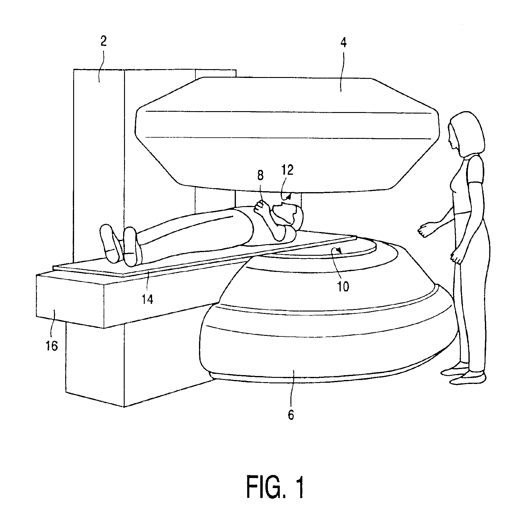
[0043]FIG. 1 is a general view of a known the vertical field type apparatus for the formation of MR images. The apparatus consists of a stand 2 which supports the lower magnetic pole 6 and the upper magnetic pole 4. It is to be noted that in the present context a magnetic pole is to be understood to mean the assembly of associated field generating coils, without it being necessary (but possible) to provide an iron circuit which interconnects the two magnetic poles so as to conduct the magnetic flux. A space for receiving a patient 8 to be examined exists between the magnetic poles. The patient to be examined is arranged on a table top 14 which itself is supported by a support 16 which forms part of the stand 2 so that the patient 8 can be arranged in the correct position and with the correct orientation between the magnetic poles 4 and 6.

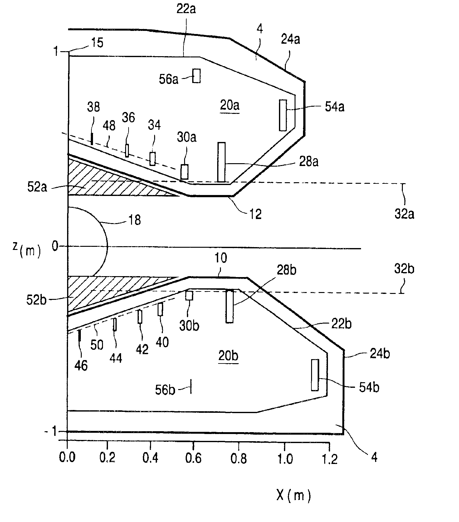
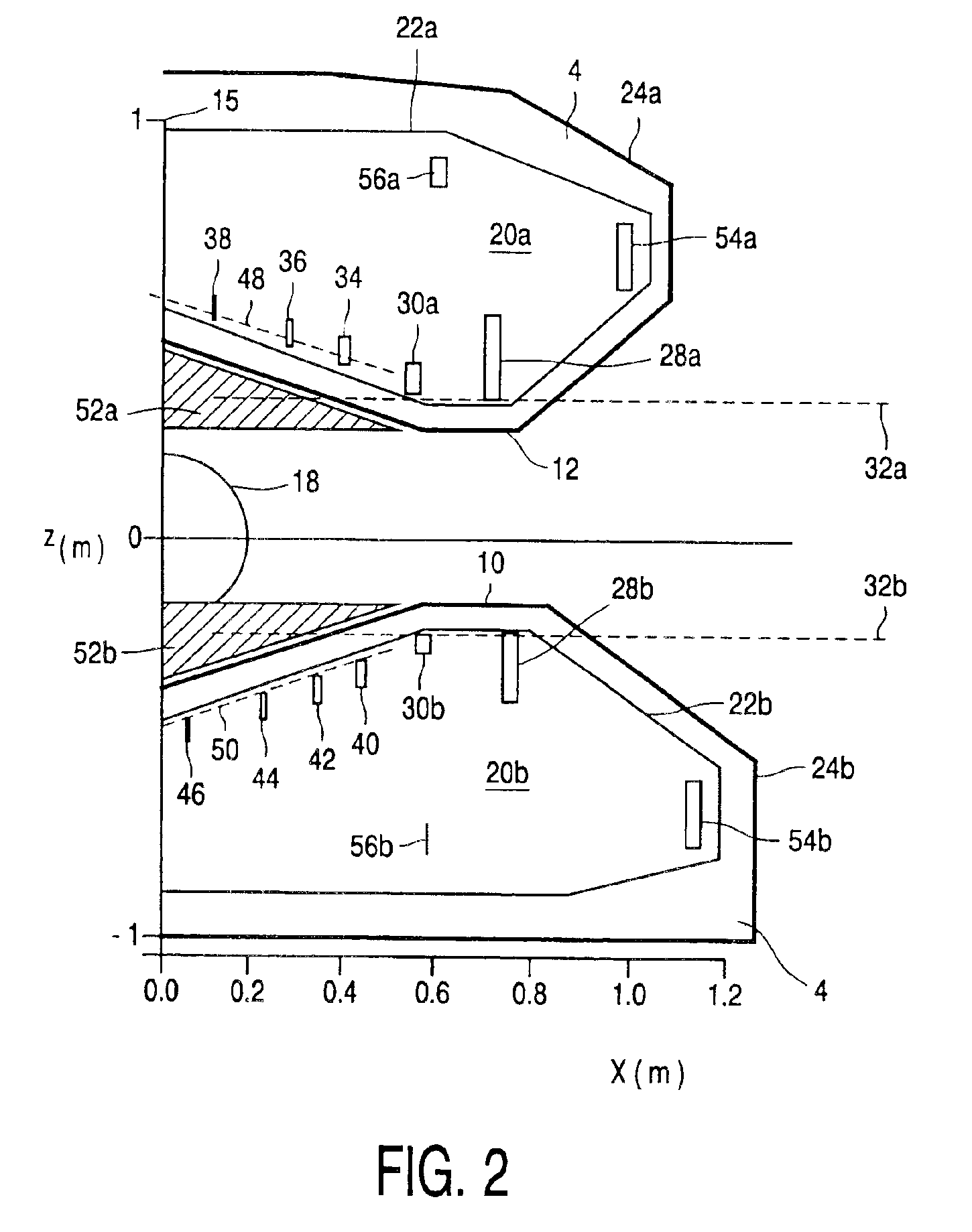
[0044]The space for accommodating the patient to be examined in customary MRI apparatus is shaped as a tunnel having a cross-section of the order o...


PUM

PropertyMeasurementUnit
pressureaaaaaaaaaa
pressureaaaaaaaaaa
distanceaaaaaaaaaa

Abstract

The invention relates to a vertical field type MRI apparatus provided with a superconducting coil system 20a, 20b for generating a substantially homogeneous magnetic field in an imaging volume 18 of the apparatus. The coil system includes a circular outer coil 28 and a supplementary coil 30 which is positioned in the same plane 32 as and within the outer coil, which coils conduct opposite currents. The ratio Da / Do of the diameter Da of the supplementary coil to the diameter Do of the outer coil lies between 0.7 and 0.9. Further coils 34 to 38, 40 to 46 for making the field even more homogeneous are preferably located on a conical surface 48, 50 within the first mentioned coils 28, 30 in such a manner that a recess is formed in which a conically shaped gradient coil system 52 can be accommodated, with the result that the expensive outer coil 28 and the supplementary coil 30 can be arranged at an as short as possible distance from the space for receiving the patient to be examined.

Description

[0001]This application is continuation of U.S. patent application Ser. No. 09 / 962,297 filed on Sep. 25, 2001, now U.S. Pat. No. 6,741,078.BACKGROUND OF THE INVENTION[0002]The invention relates to a vertical field type MRI apparatus for forming magnetic resonance images, including:[0003]at least one field generating superconducting coil system for producing a substantially homogeneous magnetic field in an imaging volume of the apparatus,[0004]which coil system includes:[0005]a round outer coil that is situated in an outer coil plane;[0006]a round supplementary coil that is situated within the outer coil.[0007]An apparatus of this kind is known from United States patent U.S. Pat. No. 5,939,962. The homogeneous magnetic field required for MR imaging in such a vertical field type apparatus is usually generated by two oppositely situated magnetic poles wherebetween the patient to be examined can be arranged. Generally speaking, said magnetic field then has a vertical direction. Apparatus...

Claims


Application Information

Patent Timeline
Patent Type & Authority Patents(United States)
IPC IPC(8): H01F6/00G01R33/3815A61B5/055G01R33/38G01R33/385G01R33/421H01F6/04
CPCG01R33/3806G01R33/3815
Inventor OVERWEG, JOHANNES ADRIANUS
Owner KONINKLIJKE PHILIPS ELECTRONICS NV
Why Eureka
Try Eureka