Micro-mirror and a method for fabricating the same

a micro-mirror and mirror technology, applied in the field of micro-mirrors, can solve the problems of reducing the dimensional accuracy of the hinge section, limiting the scanning area or extent, and affecting the operation of the device, so as to achieve the effect of wide-angle deflection, easy fabrication, and large deflection angl

Inactive Publication Date: 2006-03-07
SONY CORP
View PDF5 Cites 7 Cited by
  • Summary
  • Abstract
  • Description
  • Claims
  • Application Information

AI Technical Summary

Benefits of technology

[0011]In this micro-mirror, the movable section of the hinge section having the bi-morph structure deflects by supplying current to the first drive film, and thereby the incident light is deflected along with the change of relative angle of the mirror section to the incident light in accordance with the deflection of the movable section. As the mirror section is formed to be a cantilever beam structure that comprises the fixed section of the hinge section as a fixed end, and the mirror section as a free end, the mirror section as the free end can get larger deflection angle.
[0012]Further according to a method for fabricating a micro-mirror of the present invention, the fabrication process includes concrete processes for a micro-mirror that comprises: a mirror section for reflecting an incident light; a hinge section including a fixed section and a movable section each having a flat surface; and a drive means having a bi-morph structure made of two or more of materials of heat expansion coefficient for deflecting a relative angle of the mirror section to the incident light, wherein the hinge section and the mirror section are integrally constructed by a structured film formed on a semiconductor substrate by utilizing crystal an-isotropy of the semiconductor substrate. With these processes, the micro-mirror having a slant surface for the mirror section is easily fabricated.
[0013]According to the micro-mirror of the present invention, as the drive means of the mirror section having the reflective surface, the bi-morph structure utilizing the differences in thermal expansion coefficient of at least two materials are employed, so that it is possible to perform a high speed and wide angle deflection of the mirror section.
[0014]Particularly the micro-mirror of the present invention comprises: a hinge section including a fixed section and a movable section each having a flat surface; and a drive means having a bi-morph structure made of two or more of materials of heat coefficient for deflecting a relative angle of the mirror section to the incident light so that it becomes possible to deflect the mirror section more widely. Accordingly, it becomes possible to make a scanning area wider when applied to a laser scanner or the like.
[0015]Further, according to a method for fabricating the micro-mirror of the present invention, the mirror section and the hinge section are formed by utilizing crystal anisotropy of a semiconductor substrate, particularly a silicon substrate for example, so that the micro-mirror of this invention can be easily fabricated.

Problems solved by technology

On the contrary, as the flat surface of the substrate is directly utilized, its deflection angle is limited to a certain limited extent, so that a scanning area or extent is restricted when used as a scanner.
Further in the conventional micro-mirror, the hinge section is fabricated by forming an aperture by etching, but generally, defects are frequently generated at corners of the aperture, so that if the aperture is formed only within a single surface (crystalline plane) as conventional, it causes a problem where the hinge section is tend to be destroyed by the concentration of the stress at the defect section upon driving.
Further, there exists another problem where a dimensional accuracy of the hinge section is largely degraded by over-etching upon forming the aperture.

Method used


Image

  • Micro-mirror and a method for fabricating the same
  • Micro-mirror and a method for fabricating the same
  • Micro-mirror and a method for fabricating the same

Examples


Embodiment Construction

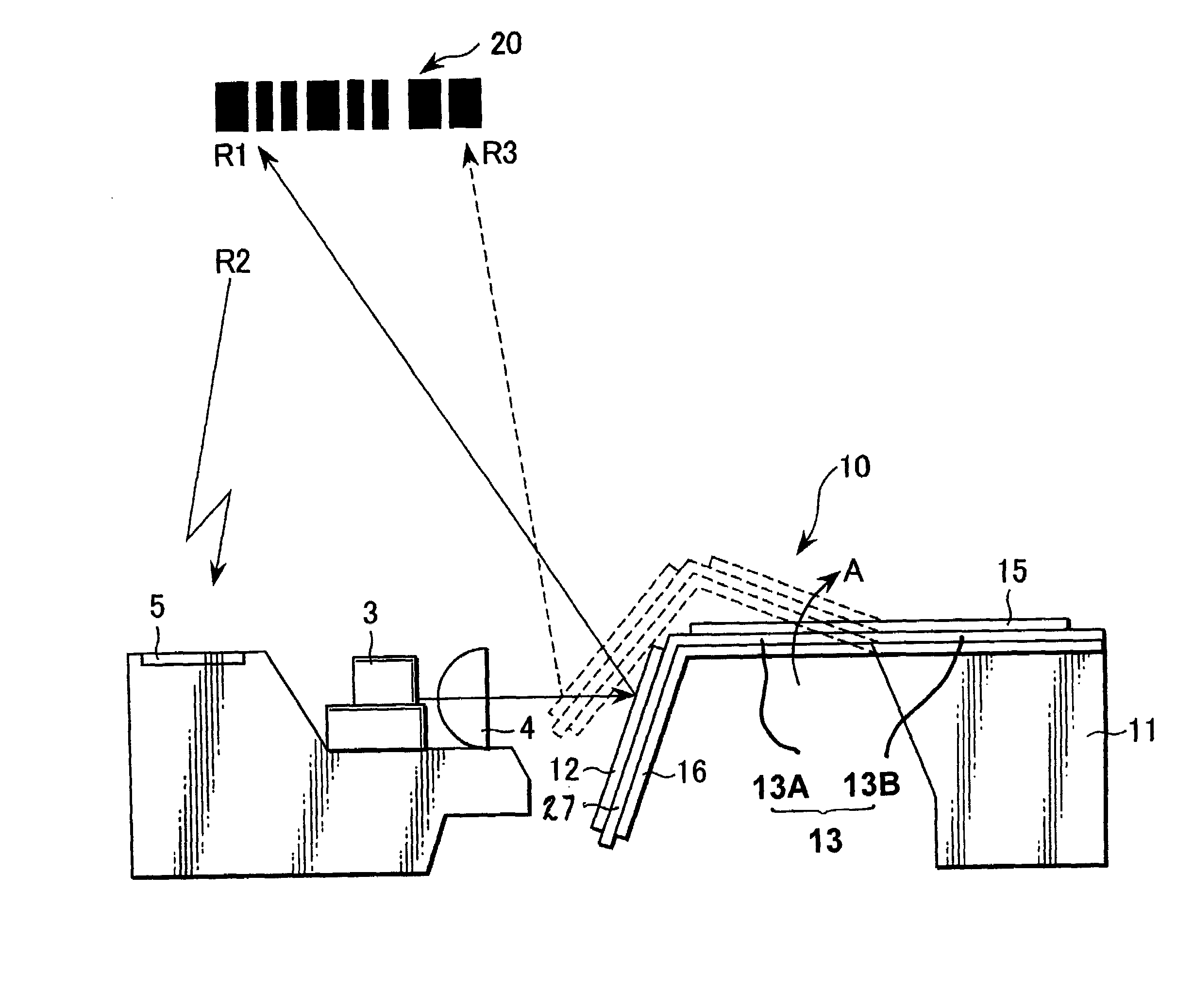
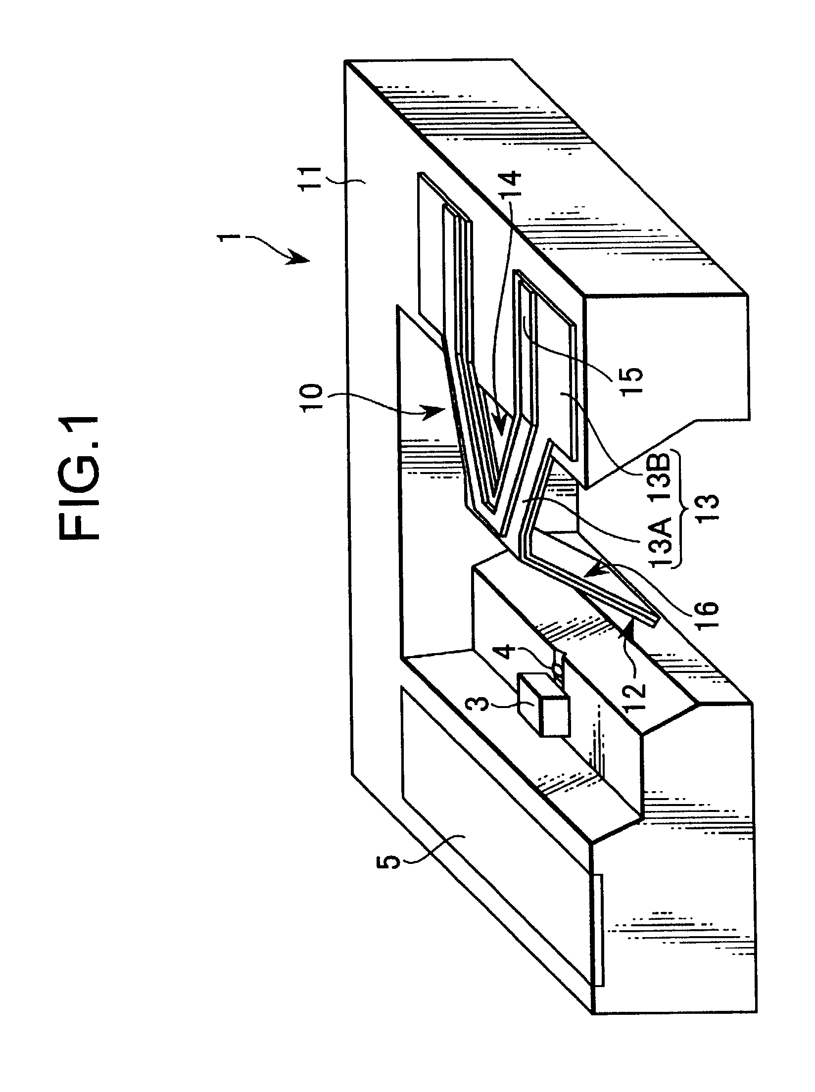
[0026]Now, one of embodiments of the present invention will be explained with reference to the accompanying drawings. FIG. 1 shows a construction of a laser scanner (a bar-code scanner, for example) using a micro-mirror of the present invention, wherein a laser scanner 1 scans a bar-code with a laser beam irradiated from a laser diode 3 and converged at a micro-lens 4 by deflecting the laser beam with a micro-mirror 10, then, its reflected light (a return beam) is detected by a photo diode 5. These micro-mirror 10 and the photo diode 5 are fabricated using a common silicon substrate 11 as will be described later.

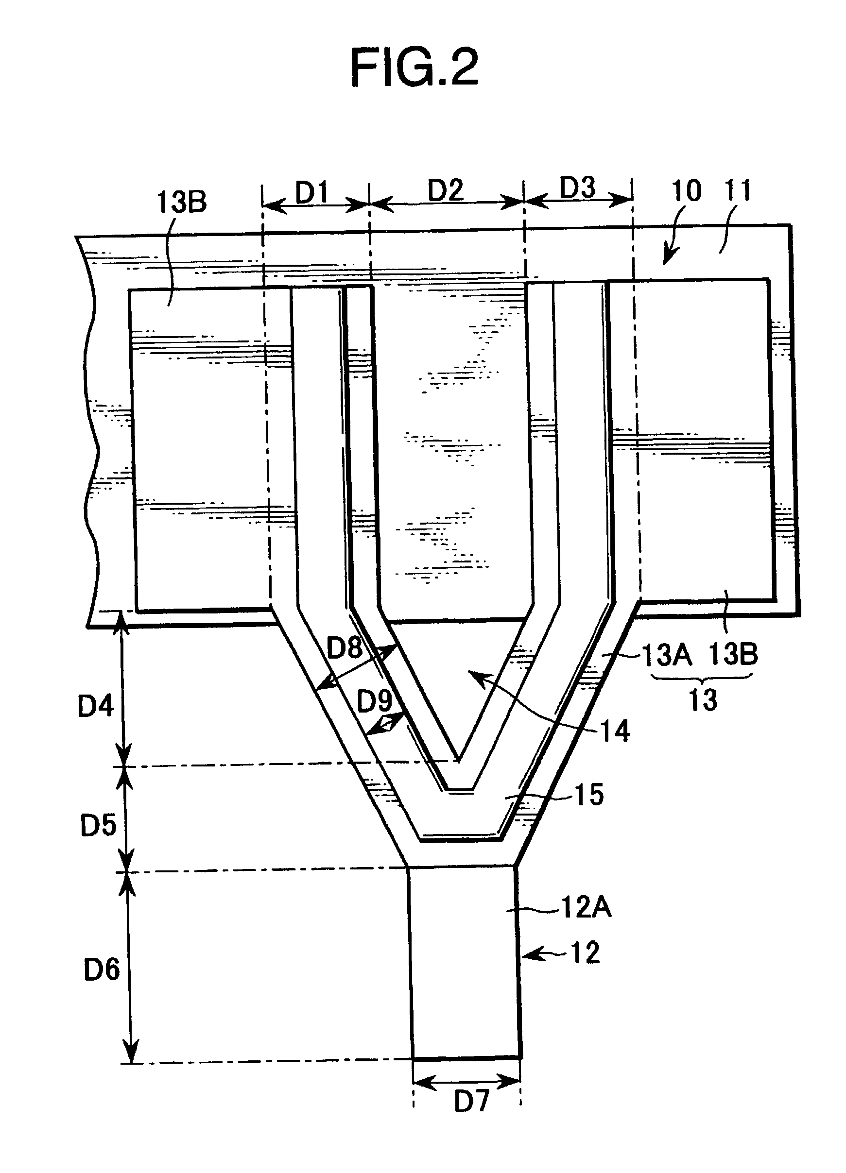
[0027]The micro-mirror 10 is opposite to the laser diode 3, and has a mirror section 12 having a slant surface and a flat-shaped hinge section 13 where the mirror section 12 side is a free end and the hinge section 13 side is a fixed end. For example, the hinge section 13 is formed to have a near V-shaped form for positioning a triangle aperture 14 in-between, and comprises ...


PUM

PropertyMeasurementUnit
angleaaaaaaaaaa
angleaaaaaaaaaa
deflection angleaaaaaaaaaa

Abstract

A micro-mirror for deflecting an incident light is disclosed, wherein the micro-mirror comprises: a mirror section for reflecting an incident light issued from a laser diode; a hinge section including a fixed section and a movable section each having a flat surface; and a drive section having a bi-morph structure made of two or more of materials having different heat expansion coefficient for deflecting said mirror section to change relative angle to said incident light.

Description

CROSS REFERENCE TO RELATED APPLICATIONS[0001]This application claims priority from Japanese Priority Document No. 2001-065070, filed on Mar. 8, 2001 with the Japanese Patent Office, which document is hereby incorporated by reference.BACKGROUND OF THE INVENTION[0002]1. Field of the Invention[0003]This invention relates to a micro-mirror applied to a MEMS (Micro Electro Mechanical Systems) and a method for fabricating such micro-mirror, and particularly this invention relates to a micro-mirror suitable for document scanning application and a method for fabricating the same.[0004]2. Description of the Related Art[0005]A micro-mirror (namely, a scanning mirror) is fabricated by a micro machining using a silicon substrate as a part applied to a laser scanner, for example. In a conventional micro-mirror such as described in an article [Technical Digest of the 16th Sensor Symposium, 1998 pp. 167–170], for example, a flat surface section of a silicon substrate is made to be a mirror surface...

Claims


Application Information

Patent Timeline
Patent Type & Authority Patents(United States)
IPC IPC(8): G02B26/08B81B3/00B81C1/00G02B26/10
CPCG02B26/0833G02B26/0866Y10S359/904
Inventor HARA, MASAKIMAKINO, TAKUYAHORI, KAZUHITOHANE, KAZUHIROSASAKI, MINORU
Owner SONY CORP
Why Eureka
Try Eureka