Method and a measuring circuit for determining temperature from a PN junction temperature sensor, and a temperature sensing circuit comprising the measuring circuit and a PN junction

a temperature sensor and measuring circuit technology, applied in heat measurement, instruments, pulse techniques, etc., can solve the problems of inability to measure the base/emitter voltage of the transistor, failure to cancel the effect of current path series resistance in the output voltage, and inability to use low voltage switched current temperature sensing circuits with more than two excitation currents. , to achieve the effect of facilitating the measurement of the operating temperature of the integrated circuit, reducing the number of pins, and accurate representation of the temperatur

Active Publication Date: 2006-03-07
ANALOG DEVICES INC
View PDF9 Cites 92 Cited by
  • Summary
  • Abstract
  • Description
  • Claims
  • Application Information

AI Technical Summary

Benefits of technology

[0102]The advantages of the invention are many. By virtue of the fact that the method and the measuring circuit eliminate the effect of current path series resistance, the resulting voltage outputted by the measuring circuit after a measuring cycle, which is indicative of the temperature of the device, the temperature of which is being measured, is an accurate representation of the temperature of the device. Additionally, by virtue of the fact that the effect of current path series resistance on the output voltage which is indicative of the temperature of the device is eliminated, the excitation currents may be applied to the device on the same lines as the voltages developed across the device resulting from the excitation currents are applied to the measuring circuit. This, thus, permits accurate measuring of the temperature of the device, the temperature of which is to be measured with two wires only.
[0103]This is a particularly important advantage in integrated circuits, where minimisation of pin count is critical. For example, it is common in the fabrication of integrated circuits to embed a temperature sensor device, for example, a substrate bipolar transistor within the integrated circuit for facilitating measuring of the operating temperature of the integrated circuit. The embedded device typically is connected to two pins only of the integrated circuit. The device may be provided within the integrated circuit a considerable distance from the two pins, thus resulting in line series resistance between the device and the pins. The provision of only two pins requires that the excitation currents and the measuring of the voltages developed across the device resulting from excitation of the device by the excitation currents must be carried out on the same two pins. However, by eliminating the effect of current path series resistance, each excitation current may be applied to the device through the two pins, and the resulting voltage developed across the device resulting from the excitation current can be simultaneously measured on the same two pins without adversely affecting the temperature measurement.
[0104]Additionally, by virtue of the fact that the effect of current path series resistance is eliminated permits the measuring circuit to be located remotely of the device, the temperature of which is to be measured, thereby permitting the measuring circuit to be located in any convenient location in a system where the temperature of the device is to be measured by the measuring circuit. Furthermore, the measuring circuit can be connected to the device by two wires only, and the excitation currents can be applied to t

Problems solved by technology

In many switched current temperature sensing circuits, it is not possible to measure the base/emitter voltage of the transistor directly at the transistor.
However, while the temperature sensing circuit of Miranda operates to remove the dependence on saturation current in the measuring transistor, the temperature sensing circuit of Miranda, since it operates with tw

Method used


Image

  • Method and a measuring circuit for determining temperature from a PN junction temperature sensor, and a temperature sensing circuit comprising the measuring circuit and a PN junction
  • Method and a measuring circuit for determining temperature from a PN junction temperature sensor, and a temperature sensing circuit comprising the measuring circuit and a PN junction
  • Method and a measuring circuit for determining temperature from a PN junction temperature sensor, and a temperature sensing circuit comprising the measuring circuit and a PN junction

Examples


Embodiment Construction

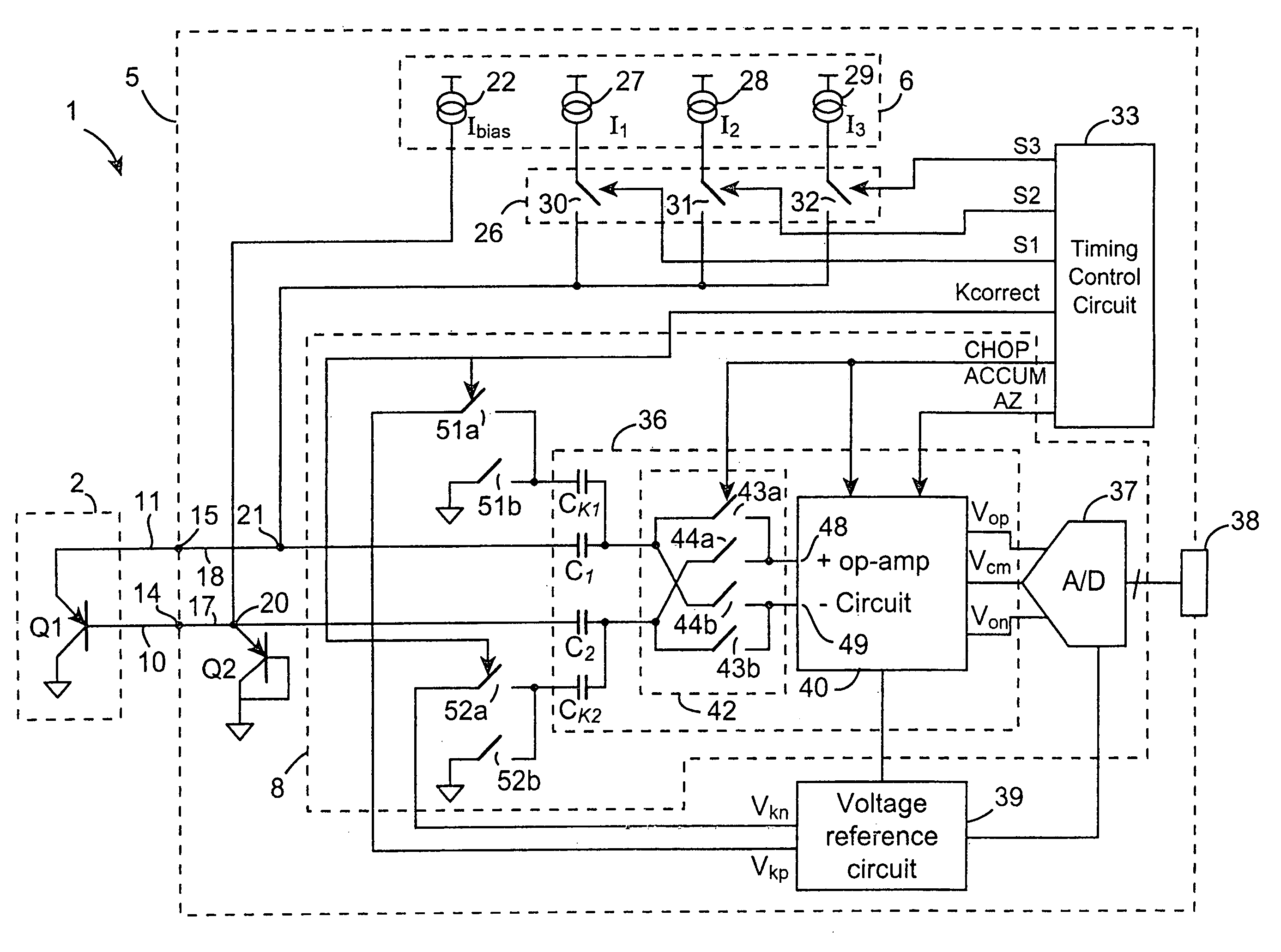
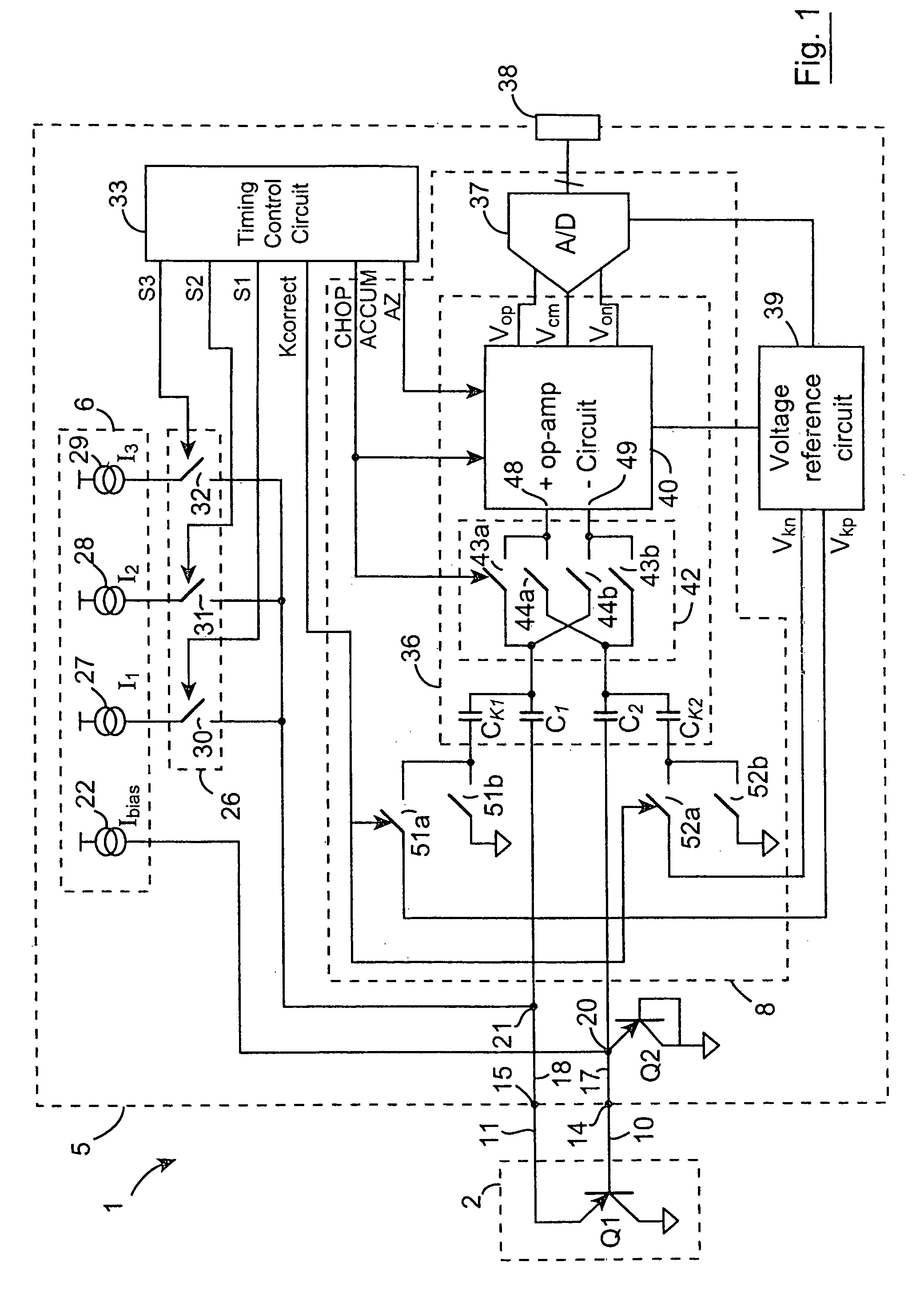
[0118]Referring to the drawings, there is illustrated a switched current temperature sensing circuit according to the invention, indicated generally by the reference numeral 1, for determining temperature sensed by a temperature sensor 2, which comprises a PN junction. In this embodiment of the invention the PN junction of the sensor 2 is provided by a PNP substrate bipolar measuring transistor Q1, the collector of which is connected to a fixed voltage, in this case ground, and which is formed by a CMOS process. The measuring transistor Q1 is selected so that its current gain is substantially constant over its operating range of collector currents, in order to avoid current gain errors in the measured results. In this embodiment of the invention the measuring transistor Q1 is selected so that the current gain variation over the operating range of the collector currents is less than 1%. A measuring circuit 5 also according to the invention which forms a part of the temperature sensin...


PUM


Abstract

A switched current temperature sensing circuit (1) comprises a measuring transistor (Q1) which is located remotely of a measuring circuit (5) which applies three excitation currents (I1,I2,I3) of different values to the measuring transistor (Q1) in a predetermined current sequence along lines (10,11). Resulting base/emitter voltages from the measuring transistor (Q1) are applied to the measuring circuit (5) along the same two lines (10,11) as the excitation currents are applied to the measuring transistor (Q1). Voltage differences ΔVbe of successive base/emitter voltages resulting from the excitation currents are integrated in an integrating circuit (36) of the measuring circuit (5) to provide an output voltage indicative of the temperature of the measuring transistor (Q1). By virtue of the fact that the measuring transistor (Q1) is excited by excitation currents of three different values, the effect of current path series resistance in the lines (10,11) on the output voltage indicative of temperature is eliminated. The predetermined current sequence in which the excitation currents are applied to the measuring transistor (Q1) is selected to minimize the voltages in the integrating circuit (36) during integration of the voltage differences ΔVbe.

Description

FIELD OF THE INVENTION[0001]The present invention relates to a measuring circuit and a method for determining temperature from a device which exhibits an exponential relationship between temperature and voltage in response to an excitation current. Such devices are typically semiconductor devices which include a PN junction, and commonly, are used as temperature sensors. The invention also relates to a temperature sensing circuit incorporating the measuring circuit and such a device acting as a temperature sensor. In particular, the invention relates to such a measuring circuit, a method for determining temperature of such a device, and a temperature sensing circuit in which the effect of series resistance in the current path between the sensor device and the measuring circuit, including series resistance of the device, is minimized or eliminated.BACKGROUND TO THE INVENTION[0002]Temperature sensing using a device which exhibits an exponential relationship between temperature and vol...

Claims


Application Information

Patent Timeline
IPC IPC(8): G01K7/00
CPCG01K7/01
Inventor LILLIS, ELIZABETH A.CLEARY, JOHN A.MIRANDA, EVALDO M.
Owner ANALOG DEVICES INC
Why Eureka
Try Eureka