Lead wire attachment method, electrode, and spot welder

a lead wire and electrode technology, applied in the direction of spinal electrodes, electrotherapy, therapy, etc., can solve the problems of difficulty in attaching a lead wire to the electrode element, high cost of materials, and inability to use high purity materials for common applications

Inactive Publication Date: 2006-03-14
NIHON KOHDEN CORP
View PDF9 Cites 13 Cited by
  • Summary
  • Abstract
  • Description
  • Claims
  • Application Information

AI Technical Summary

Benefits of technology

[0015]The present invention aims at providing a method which enables easy attachment of a lead wire onto a titanium member; an electrode having a lead wire attached thereto by means of the method; and a spot welder to be used for manufacturing the electrode.
[0016]According to the present invention, a lead wire attachment method for attaching a lead wire to a first member made from titanium is provided in that a second member made from solderable material is attached to the first member by spot welding, and the lead wire is attached to the second member by soldering. As a result, sufficient strength is ensured in attaching a leadwire. Further, an electrode which dissolves a smaller amounts of ion can be manufactured at lower cost.
[0017]Preferably, one of a pair of welding electrodes to be used for spot welding is brought into contact with the first member, and a contact surface of the electrode is formed so as to become larger than a contact surface present between the first and second members. As a result, no damage arises in a contact surface between the first member and the welding electrode, which would otherwise be caused by electric spark.
[0021]An electrode according to the present invention comprises a first member made from titanium; a second member which is attached to the first member by spot welding and is made from solderable material; and a lead wire soldered at one end thereof to the second member. As a result, sufficient strength is ensured in attaching a lead wire. Further, ions are dissolved in a small amount, and the electrode is less expensive.
[0027]wherein a surface of one of said welding electrodes to contact with one of said members is sufficiently larger than that of the other welding electrode to contact with the other member so as not to cause damage by electric spark.
[0028]Further, according to the present invention, there is provided a method for welding two members with a spot welder comprising a first and a second welding electrodes for clamping said two members, letting current flow therebetween and welding said two members, wherein a surface of said first welding electrode to contact with one of said members is sufficiently larger than that of the second welding electrode to contact with the other member so as not to cause damage by electric spark, comprising steps of: clamping a titanium member and a copper plate with said first and second welding electrodes so that the surface of said first welding electrode contacts with said titanium member and the surface of said second welding electrode contacts with said copper plate; and letting current flow therebetween to welder said titanium and said copper plate.

Problems solved by technology

However, when stainless steel is used as an electrode element for electrical simulation, the following problems arise.
As a result, the electrode element undergoes reduction in strength and deterioration in appearance.
However, these substances are expensive and inappropriate for employment of high purity materials for common applications, such as a biomedical electrode.
However, pits or pin holes or loss of a plating layer due to a deficiency in mechanical strength results in exposure of stainless steel, thus causing dissolve of ions by a galvanic current.
Hence, when titanium is used as an electrode element, difficulty is encountered in attaching a lead wire to the electrode element.
For this reason, no electrode structure in which a lead wire is readily attached to a titanium electrode element has hitherto been available, and an attachment method is complicated (as described in Examined Japanese Patent Publication No. 45622 / 1981 and U.S. Pat. No. 3,749,101).

Method used


Image

  • Lead wire attachment method, electrode, and spot welder
  • Lead wire attachment method, electrode, and spot welder
  • Lead wire attachment method, electrode, and spot welder

Examples


Embodiment Construction

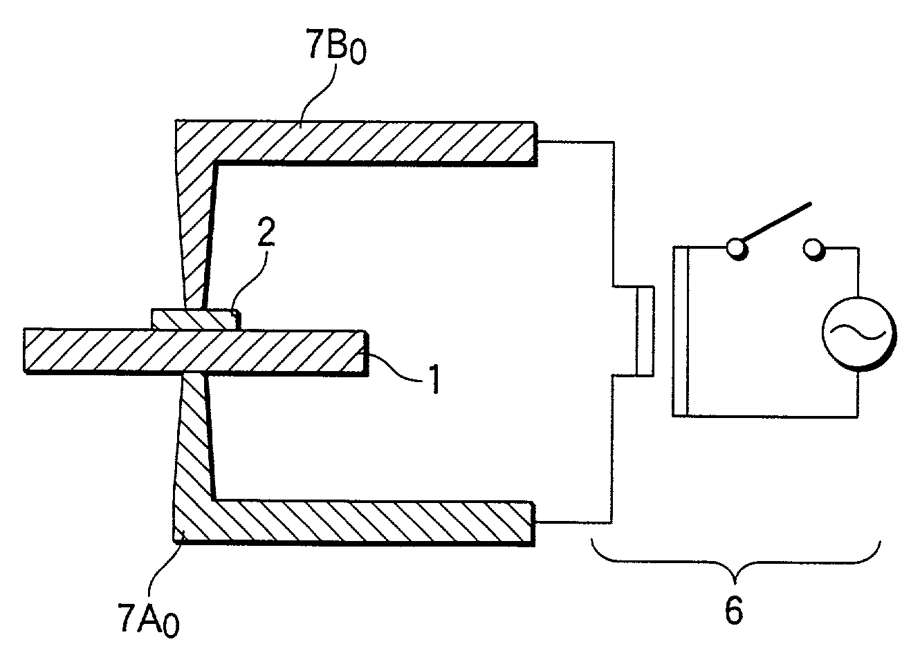
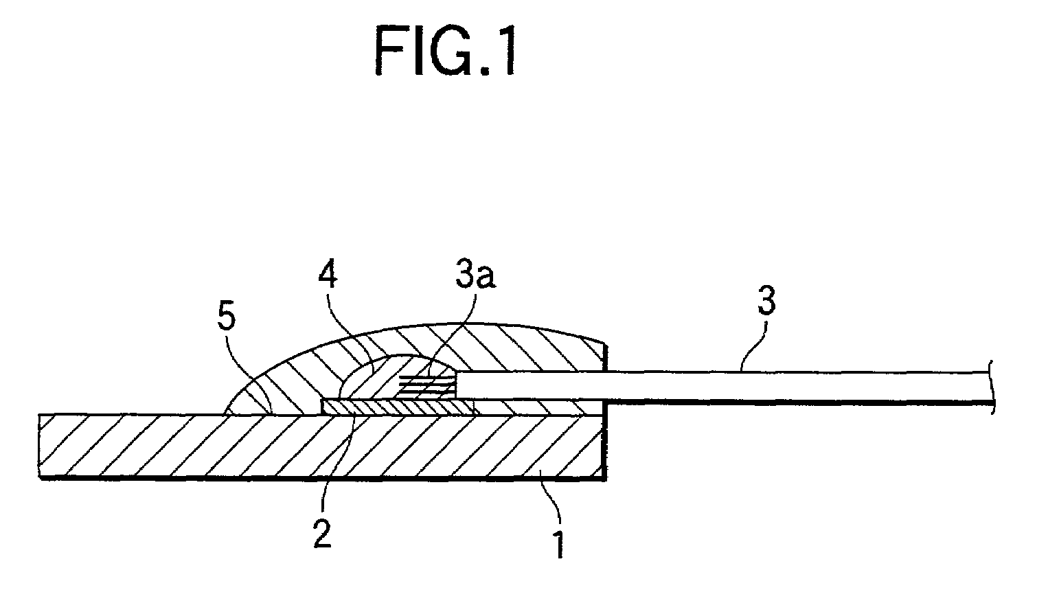
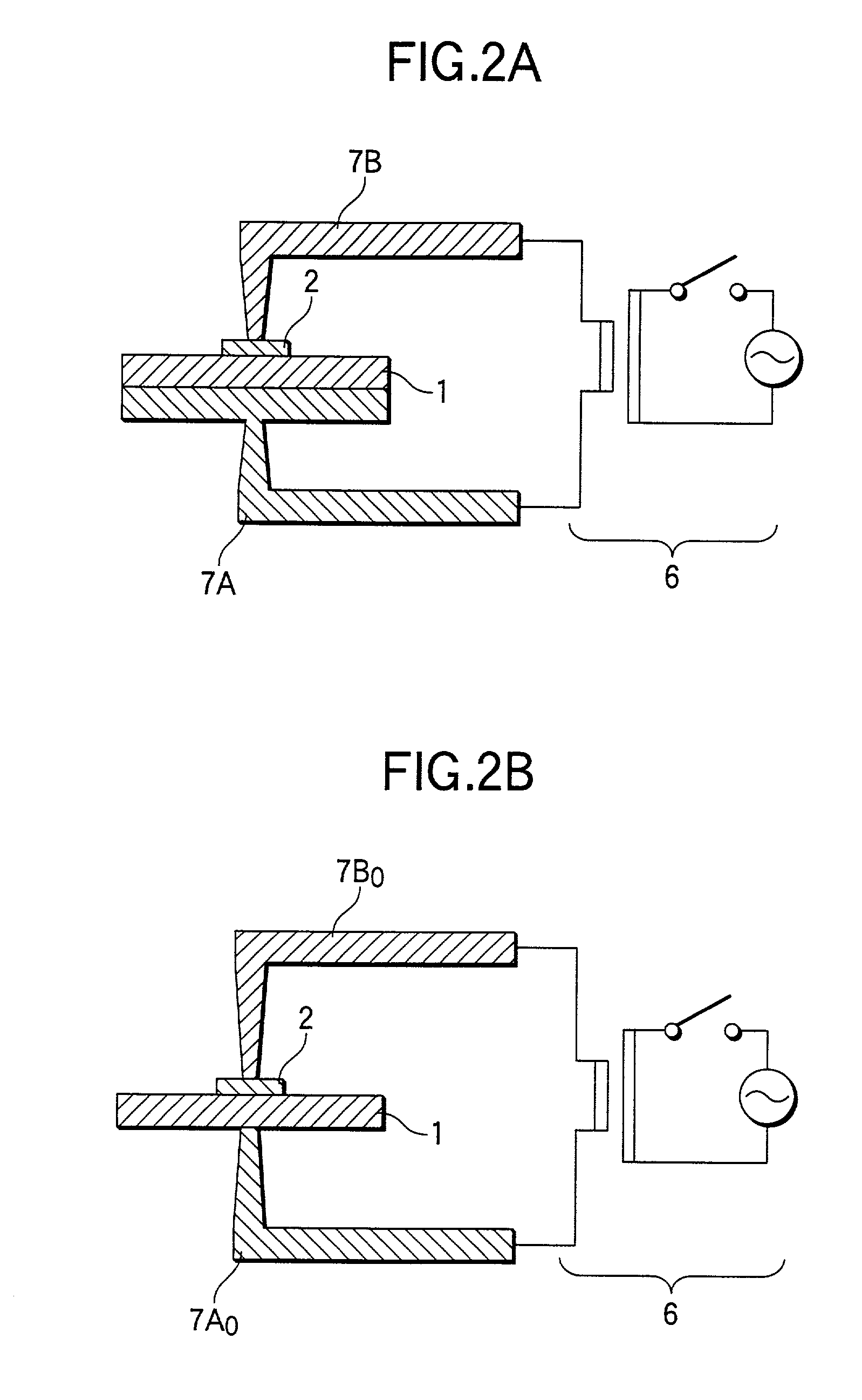
[0038]FIG. 1 shows a basic type biomedical electrostimulating electrode according to the present invention. In the present embodiment, the electrode is to be used for electroanesthesia. An electrode element 1 employed herein is formed from titanium and assumes the shape of a disk. A copper plate 2 is mounted on top of the electrode element 1 by spot welding. One end of a conductor section 3a of a lead wire assy 3 is soldered to the top of the copper plate 2 by solder 4. The solder 4, the copper plate 2, and the end of the lead wire assy 3 are covered with an insulation section 5. For instance, epoxy resin or silicon resin is used for the insulation section 5.

[0039]In order to produce such an electrode, the copper plate 2 is mounted on the electrode element 1 by spot welding. Next, one end of the lead wire 3a of the lead wire assy 3 is soldered to the copper plate 2. Further, the solder 4, the copper plate 2, and the end of the lead wire assy 3 are coated, to thereby form the insulat...


PUM

PropertyMeasurementUnit
Corrosionaaaaaaaaaa
strengthaaaaaaaaaa
purityaaaaaaaaaa

Abstract

A copper plate 2 is mounted on a titanium electrode element 1 by spot welding, and a lead wire 3a is attached to the copper plate 2 by solder 4.

Description

BACKGROUND OF THE INVENTION[0001]1. Field of the Invention[0002]The present invention relates to a method of mounting a lead wire on a titanium member, an electrode having a lead wire mounted thereon by the method, and a spot welder used for manufacturing the electrode.[0003]2. Related Art[0004]Stainless steel, for example, has hitherto been used as an electrode element for a biomedical electrode to be used for electrically stimulating a living body from a body surface.[0005]However, when stainless steel is used as an electrode element for electrical simulation, the following problems arise.[0006](1) Corrosion arises in an electrode element as a result of energization, thereby inducing dissolve of ions, such as iron ions, nickel ions, and chromium ions. As a result, the electrode element undergoes reduction in strength and deterioration in appearance.[0007](2) The thus-dissolved ions (particularly nickel ions and chromium ions) induce contact dermatitis or an allergic reaction.[0008...

Claims


Application Information

Patent Timeline
Patent Type & Authority Patents(United States)
IPC IPC(8): H01R43/02A61N1/04A61N1/05
CPCA61N1/0456A61N1/046A61N1/048A61N1/0551A61N1/0408Y10T29/49179Y10T29/49002Y10T29/49117Y10T29/49174Y10T29/49213Y10T29/49208
Inventor SUDA, SHINKURATA, TOHRU
Owner NIHON KOHDEN CORP
Why Eureka
Try Eureka