Light-emitting device and light-emitting display with a polarization separator between an emissive layer and a phase plate

a technology of polarization separator and light-emitting display, which is applied in the direction of luminescnet screens, discharge tubes, identification means, etc., can solve the problems of short response time of display, deterioration of device efficiency, and decrease of contrast ratio, so as to reduce incident reflection and contribute to the effect of display efficiency

Inactive Publication Date: 2006-03-14
SAMSUNG DISPLAY CO LTD +1
View PDF25 Cites 26 Cited by
  • Summary
  • Abstract
  • Description
  • Claims
  • Application Information

AI Technical Summary

Benefits of technology

[0018]The invention is made in consideration of the above problems, it is an object of the invention to provide light-emitting devices such as organic EL devices or the like in which by allowing light emitted from an emissive layer to efficiently contribute to a display, the bright display is realized and, at the same time, by reducing the

Problems solved by technology

Thus, there is a feature such that it is thin and light-weighted, further, a viewing angle is wide, and a response time of display is short.
That is, there is a problem such that the black display does not become dark under an environment where the ambience is bright, and a contrast ratio decreases.
According to this system, if color changing efficiency is low, device efficiency deteriorates.
According to the direct-patterning approach, since it is necessary to form three kinds of devices onto the same substrate, the manufacturing process becomes slightly complicated.
However, upo

Method used


Image

  • Light-emitting device and light-emitting display with a polarization separator between an emissive layer and a phase plate
  • Light-emitting device and light-emitting display with a polarization separator between an emissive layer and a phase plate
  • Light-emitting device and light-emitting display with a polarization separator between an emissive layer and a phase plate

Examples


embodiment 1

(Embodiment 1 of the Light-emitting Displays)

[0106]Light-emitting displays in which a plurality of light-emitting elements of the invention are aligned and arranged, the light emitting operations of the plurality of light-emitting devices are controlled, and a display is performed will now be described. FIG. 7 is a block diagram schematically showing a whole layout of a light-emitting display 1 according to the invention. FIG. 8 is an equivalent circuit diagram of an active matrix constructed in a display area 2.

[0107]As shown in FIG. 7, in the display 1, the display area 2 is formed in almost a center portion of a substrate 6. A data driving circuit 3 for outputting an image signal to a data line 7 is formed on the upper side of the display unit 2 and a scan driving circuit 4 for outputting a scan signal to a gate line 8 is formed on the left side. Each of the driving circuits 3 and 4 is constructed by a shift register circuit a level shifting circuit, an analog switching circuit, ...

embodiment 2

(Embodiment 2 of the Light-emitting Displays)

[0165]Another embodiment of the light-emitting displays in the invention will now be described. FIG. 16 is a partial cross sectional view showing an outline of the light-emitting display of the invention. Since a fundamental construction of the display is substantially the same as that of the foregoing embodiment except that the light-emission color of organic layers 110W is white and the display has color filters, the same and corresponding portions are designated by the same reference numerals and their detailed descriptions are omitted.

[0166]As shown in FIG. 16, according to the present display, in the embodiment described with reference to FIG. 11, all of the organic layers which were pattern-formed to R, G, and B are replaced with the organic layers 110W of white light emission, and color filters 900R, 900G, and 900B for transmitting the lights corresponding to R, G, and B are pattern-formed between the second substrate 90 and the po...


PUM


Abstract

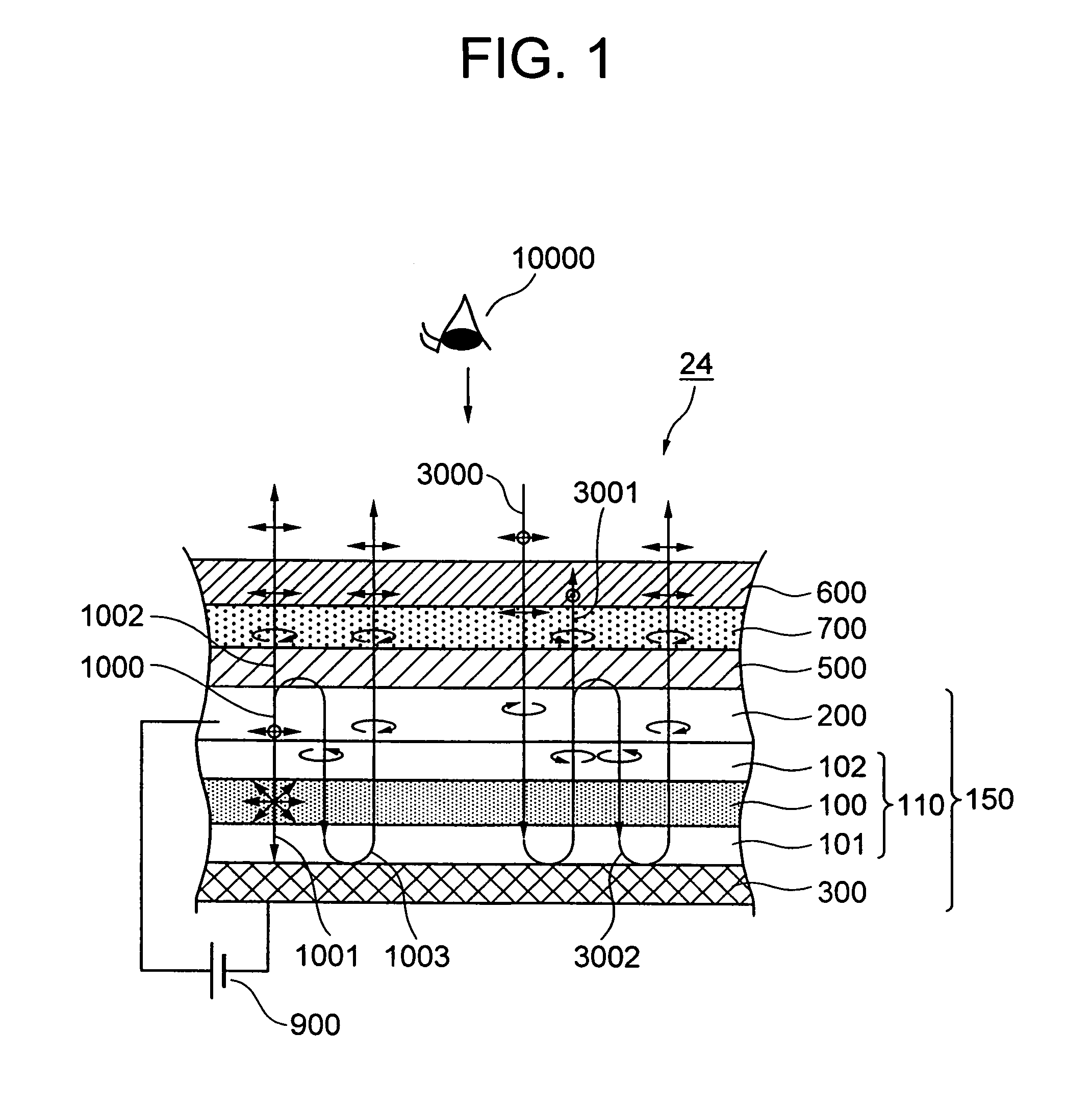
Light-emitting devices and light-emitting displays for realizing bright display by allowing light emitted from an emissive layer to efficiently contribute to a display. Polarization separators are arranged between the emissive layer and a phase plate. In the light of a wavelength range which includes a part or all of a light-emission wavelength range of the emissive layer and is narrower than a visible wavelength range and is directed from the emissive layer side to the polarization separators side, the polarization separators reflect circularly polarized light components which are converted into linearly polarized light that is absorbed by the polarizer due to the operation of the phase plate and transmit the other light.

Description

[0001]This application is a continuation of application Ser. No. 09 / 940,887, filed Aug. 29, 2001, the subject matter of which is incorporated by reference herein.BACKGROUND OF THE INVENTION[0002]The invention relates to light-emitting devices and light-emitting displays for controlling the light-emitting operations of the light-emitting devices and displaying. More particularly, the invention relates to light-emitting devices such as organic electroluminescence devices having light reflective elements on the back side of an emissive layer and to a technique which is effective when it is used for displays having such light-emitting devices.[0003]An organic electroluminescence device (hereinafter, referred to as an organic EL device) is a device such that by injecting electrons into an emissive layer comprising an organic thin film, an electric energy is converted into a light energy and light is emitted. Unlike a light-emitting display of the non-emissive type represented by a liquid...

Claims


Application Information

Patent Timeline
IPC IPC(8): H05B33/00H01L51/50G09F9/30H01L27/32H01L51/52
CPCH01L27/3211H01L27/322H01L51/5281H01L51/5284H01L51/5293H01L27/3244Y10S428/917H01L27/3295H10K59/35H10K59/38H10K59/122H10K59/12H10K50/865H10K50/868H10K50/86H05B33/00
Inventor ADACHI, MASAYAKANEKO, YOSHIYUKIARATANI, SUKEKAZUISHIHARA, SHINGO
Owner SAMSUNG DISPLAY CO LTD
Why Eureka
Try Eureka