Switching power supply device

a power supply device and power supply technology, applied in the direction of electric variable regulation, process and machine control, instruments, etc., can solve the problems of power factor reduction, power loss, conversion efficiency drop, etc., to reduce unnecessary power consumption, reduce driving voltage, and reduce unnecessary power consumption

Inactive Publication Date: 2006-03-14
SHARP KK
View PDF11 Cites 26 Cited by
  • Summary
  • Abstract
  • Description
  • Claims
  • Application Information

AI Technical Summary

Benefits of technology

[0011]An object of the present invention is to solve the above problems and to provide a switching power supply device capable of stopping operating a power-factor improvement control circuit in a low-power consumption state and contributing further to power savings.
[0012]To achieve the above object, according to one aspect of the present invention, there is provided a switching power supply device comprising a booster chopper circuit for receiving a first DC voltage and converting the first DC voltage to a second DC voltage for outputting, the booster chopper circuit including a power-factor improvement control circuit for improving a power factor, a series circuit to which the second DC voltage is supplied and comprising a primary winding of a transformer and a switching element, a switching control circuit for performing an oscillation function so as to drive and control the switching element so that a secondary winding of the transformer induces a voltage that is then rectified, smoothed, and supplied to a load as a third DC voltage, the switching control circuit for performing also, when the load is smaller than a predetermined value, an intermittent-oscillation function by which an oscillation period and a non-oscillation period are repeated, an auxiliary power supply for supplying a voltage induced in an auxiliary winding of the transformer when the switching element is driven by the switching control circuit as a driving voltage by processing the induced voltage through rectifying and smoothing to the power-factor improvement control circuit and the switching control circuit, and a voltage reduction circuit for lowering the driving voltage, wherein, during the non-oscillation period when the load is smaller than the predetermined value and the switching control circuit is performing the intermittent-oscillation function, the driving voltage supplied to the power-factor improvement control circuit drops below an operating voltage thereof through a voltage drop caused by the voltage reduction circuit and causes the power-factor improvement control circuit to stop operating so that power consumption is reduced.

Problems solved by technology

In such a switching power supply device as mentioned above, if the smoothing circuit at an input side is a capacitor-input type, there is a problem in which a power factor is reduced, because the input current flows only when a rectified voltage becomes higher than a charged voltage of an input smoothing capacitor and a conduction angle of an input current becomes smaller accordingly.
However, in comparison with a switching power supply device having no power-factor improvement function, these conventional switching power supply devices give rise to a loss of power required for operating the power-factor improvement function of the booster chopper circuit and a power conversion efficiency thereof drops accordingly.
The conventional switching power supply devices waste unnecessary power by operating the power-factor improvement function, particularly in a low-power consumption state in which improvement of the power factor is not necessary during such a period as a standby period of the electrical appliances.
To do so, the switching power supply device requires an output power sensing circuit for detecting the low-power consumption state and a power-factor improvement function control circuit for stopping the power-factor improvement function according to a control signal fed from the output power sensing circuit, which, in return, causes the circuitry to become complicated.

Method used


Image

  • Switching power supply device
  • Switching power supply device
  • Switching power supply device

Examples


first embodiment

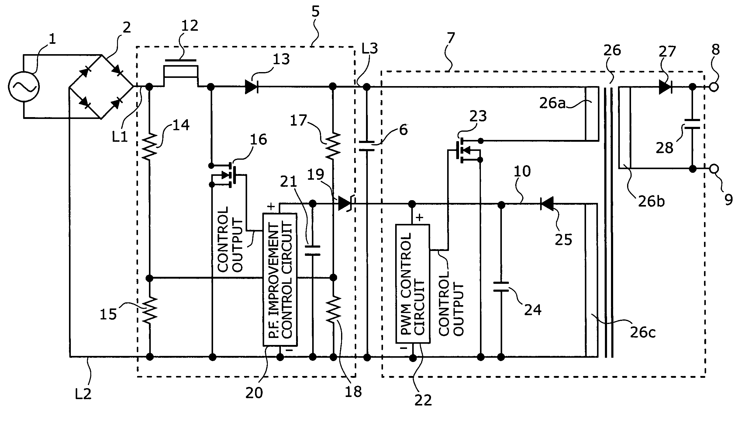
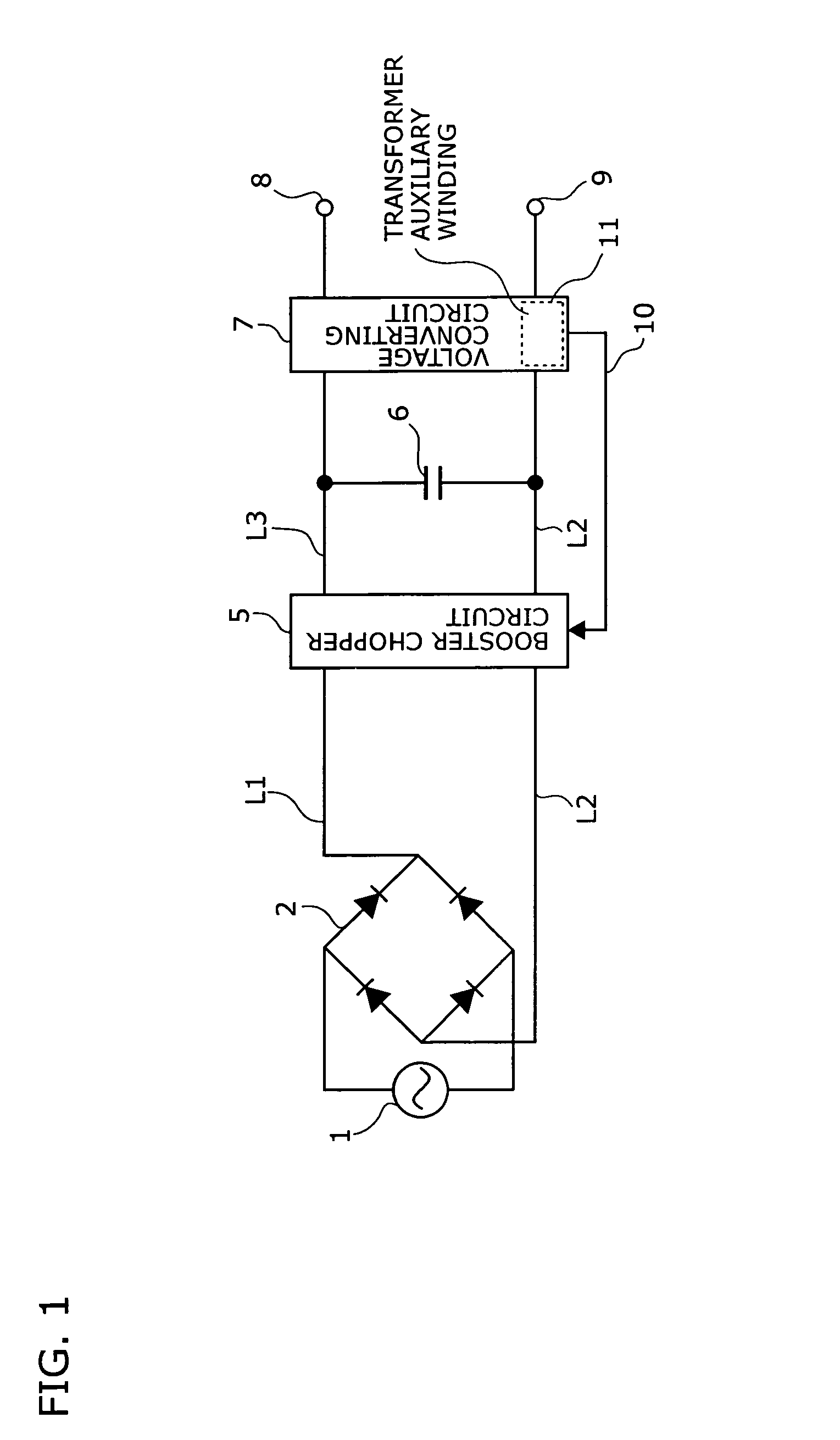
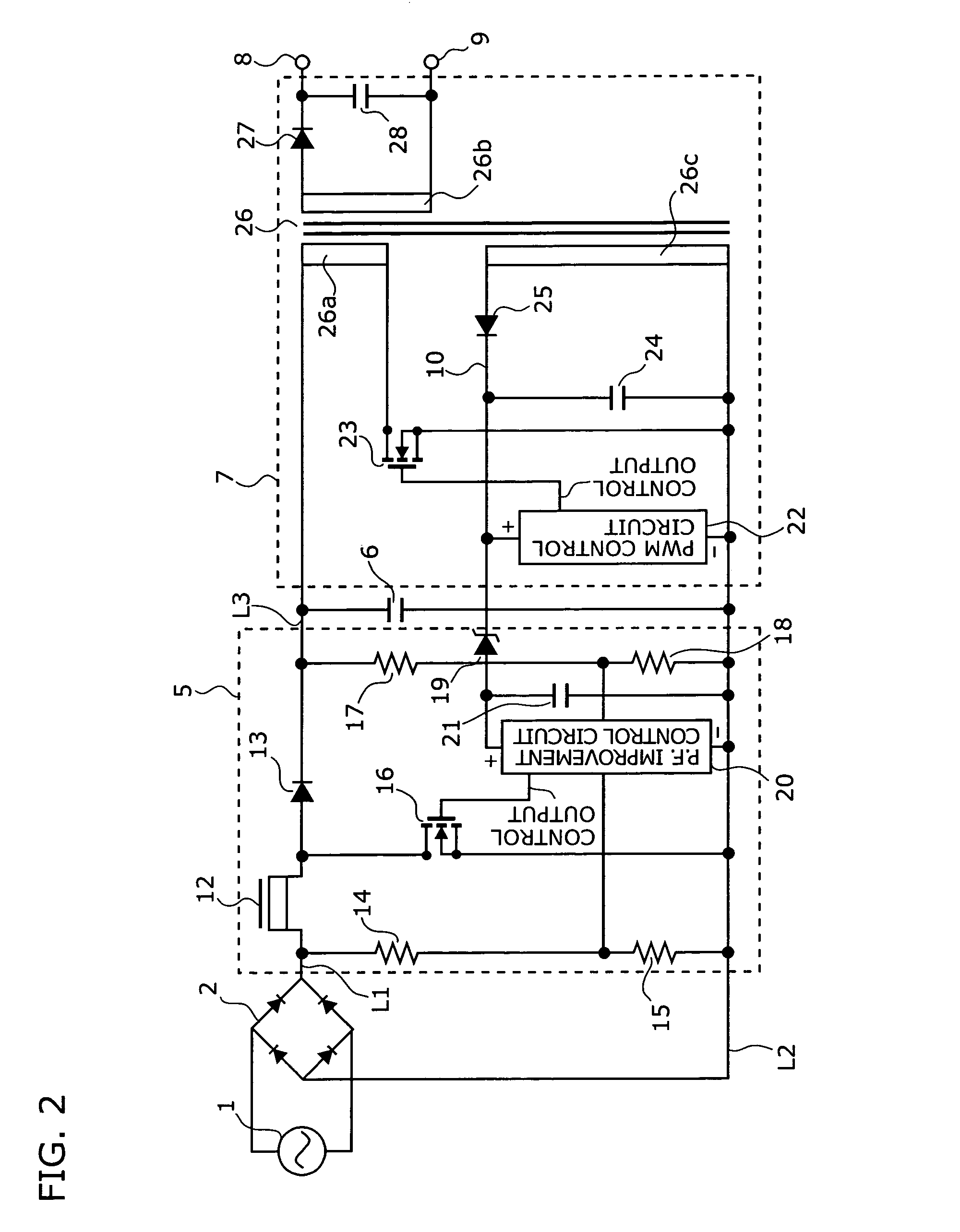
[0036]FIG. 2 is a circuit diagram of a first embodiment showing a specific configuration of the switching power supply device shown in FIG. 1. This switching power supply device employs a flyback converter circuit in accordance with a PWM (Pulse Width Modulation) control system. This switching power supply device comprises a bridge rectifier 2, a booster chopper circuit 5, a smoothing capacitor 6, and a voltage converting circuit 7.

[0037]An AC power source 1 is connected to an input side of the bridge rectifier 2, and a positive line L1 and a negative line L2 are connected to an output side of thereof. A series circuit comprising resistors 14 and 15 is connected between the positive line L1 and the negative line L2. The positive line L1 is connected to a positive line L3 by way of a chopper coil 12 and a diode 13. An FET 16 is connected between a connection point of the copper coil and the diode 13 and the negative line L2. The smoothing capacitor 6 and a series circuit comprising r...

second embodiment

[0045]FIG. 3 is a circuit diagram of a second embodiment showing a specific configuration of the switching power supply device shown in FIG. 1. In FIG. 3, such components as are found also in FIG. 2 are identified with the same reference symbols or numerals and descriptions thereof are not repeated accordingly.

[0046]A switching power supply device shown in FIG. 3 has a resistor 29 that replaces the Zener diode 19 of the switching power supply device shown in FIG. 2. When this switching power supply device is operating in a low-power consumption state and a PWM control circuit 22 is in an intermittent oscillation mode, in a period during which the PWM control circuit 22 stops functioning, a voltage induced in an auxiliary winding 26c drops. When this voltage is further reduced by being consumed as a voltage drop across the resistor 29 and by the smoothing capacitor 21 and becomes lower than an operating voltage of a power-factor improvement control circuit 20, the power-factor improv...

third embodiment

[0047]FIG. 4 is a circuit diagram of a third embodiment showing a specific configuration of the switching power supply device shown in FIG. 1. In FIG. 4, such components as are found also in FIG. 2 are identified with the same reference symbols or numerals and descriptions thereof are not repeated accordingly.

[0048]In a switching power supply device shown in FIG. 4, a diode 30 is provided in addition to a diode 25. An anode of the diode 30 is connected to one end of an auxiliary winding 26c of a transformer 26, and a cathode of the diode 30 is connected to a cathode of a Zener diode 31. This means that a power-factor improvement auxiliary power 38a arranged for a power-factor improvement control circuit 20 is provided separately from a switching control auxiliary power 38b arranged for a PWM control circuit 22. A voltage induced in the auxiliary winding 26c is rectified and smoothed by the diode 30 and a smoothing capacitor 21 and supplied to the power-factor improvement control cir...


PUM


Abstract

In a switching power supply device, the operating voltage is supplied to the power-factor improvement control circuit when the switching power supply device is operating under normal operating load. Thereby, the booster chopper circuit is controlled by the power-factor improvement control circuit so as to improve the power factor of the device. By contrast, during the non-oscillation period while the switching control circuit is in the intermittent oscillation mode when the power consumption is small, the voltage induced in the auxiliary winding drops. Accordingly, the voltage of the auxiliary power supply also drops. Furthermore, when the driving voltage to be supplied to the power-factor improvement control circuit is reduced below the operating voltage thereof by the voltage reduction circuit, the power-factor improvement control circuit stops functioning, thereby reducing power consumption accordingly.

Description

[0001]This nonprovisional application claims priority under 35 U.S.C. § 119(a) on Patent Application No. 2003-000975 filed in JAPAN on Jan. 7, 2003, which is herein incorporated by reference.BACKGROUND OF THE INVENTION[0002]1. Field of the Invention[0003]The present invention relates to a switching power supply device used as a DC power source for electrical appliances.[0004]2. Description of the Prior Art[0005]Recently, electrical appliances such as a facsimile, a telephone set, a copying machine, other office automation equipment, home electrical appliances, or the like that require a supply of electricity during a standby period in addition to an operation period have been on the rise. Because these electrical appliances need a stable constant operating voltage, a switching power supply device capable of outputting a stabilized voltage has been used. Against the background of energy conservation in recent years, in addition to reducing the power consumed by the switching power su...

Claims


Application Information

Patent Timeline
Patent Type & Authority Patents(United States)
IPC IPC(8): H02M3/335H02M7/12H02M3/28
CPCH02M1/4225H02M3/33523Y02B70/16H02M2001/007Y02B70/126H02M2001/0032Y02B70/10H02M1/0032H02M1/007
Inventor KOTSUJI, HIROTAKAKITANO, SABUROU
Owner SHARP KK
Why Eureka
Try Eureka