Fluid dynamic bearing and magnetic disk apparatus

a dynamic bearing and magnetic disk technology, applied in sliding contact bearings, instruments, physics instruments, etc., can solve the problems of static electricity charged as described above in danger of being suddenly discharged, electrically charged, air inconvenient to operate, etc., to reduce torque loss and high reliability

Inactive Publication Date: 2006-03-21
PANASONIC CORP
View PDF1 Cites 7 Cited by
  • Summary
  • Abstract
  • Description
  • Claims
  • Application Information

AI Technical Summary

Benefits of technology

[0006]The present invention is intended to solve the problems in the conventional fluid dynamic bearing and is intended to provide a fluid dynamic bearing and a magnetic disk apparatus, having heat resistance and high reliability, wherein the electrical charging on the rotation portion is prevented and the torque loss caused by the lubricant is made lower than that of the conventional fluid dynamic bearing.
[0011]a lubricant filled in the clearance between the opposed faces of the shaft and the sleeve unit, to which an ionic liquid is added as an electrical conductivity imparting agent. The fluid dynamic bearing in accordance with the present invention configured as described above can prevent the electrical charging on the rotation portion and can reduce the torque loss caused by the lubricant.
[0017]a lubricant filled in the clearance between the opposed faces of the shaft and the sleeve unt, to which linear alkyl sulfonate is added as an electrical conductivity imparting agent. The fluid dynamic bearing in accordance with the present invention configured as described above can prevent the electrical charging on the rotation portion and can reduce the torque loss caused by the lubricant.
[0021]a lubricant filled in the clearance between the opposed faces of the shaft and the sleeve unit, to which a charge transfer complex is added as an electrical conductivity imparting agent. The fluid dynamic bearing in accordance with the present invention configured as described above can prevent the electrical charging on the rotation portion and can reduce the torque loss caused by the lubricant.
[0026]a lubricant filled in the clearance between the opposed faces of the shaft and the sleeve unit, to which a mixture of an ionic polyvalent metal salt and a metal salt having a cation different from that of the ionic polyvalent metal salt is added as an electrical conductivity imparting agent. The fluid dynamic bearing in accordance with the present invention configured as described above can prevent the electrical charging on the rotation portion and can reduce the torque loss caused by the lubricant.
[0031]a motor, comprising a stator coil and a rotor magnet, for rotating the shaft or the sleeve unit. The fluid dynamic bearing in accordance with the present invention configured as described above can prevent the electrical charging on the rotation portion and can reduce the torque loss caused by the lubricant; in addition, a fluid dynamic bearing having heat resistance and high reliability can be provided.

Problems solved by technology

In addition, in the case when the fluid dynamic bearing configured as described above is used for a magnetic disk apparatus, magnetic disks cause friction with air owing to the rotation of the magnetic disks and is electrically charged.
The static electricity charged as described above is in danger of being discharged suddenly during the operation of the magnetic disk apparatus.
In the case when this kind of undesirable discharge occurred suddenly, there was a danger of causing malfunctions, such as read errors or write errors, in the magnetic disk apparatus and of causing static damage to the magnetic disks or the like.
Hence, the magnetic disk apparatus using the conventional fluid dynamic bearing was unstable in operation and had problems in reliability.
However, in the case when the electrical conductivity imparting agent was added to the lubricant as described above, the viscosity of the lubricant increased, thereby increasing torque loss during high-speed rotation and causing the degradation of the lubricant owing to heat generation due to the torque loss.

Method used


Image

  • Fluid dynamic bearing and magnetic disk apparatus
  • Fluid dynamic bearing and magnetic disk apparatus
  • Fluid dynamic bearing and magnetic disk apparatus

Examples


embodiment 1

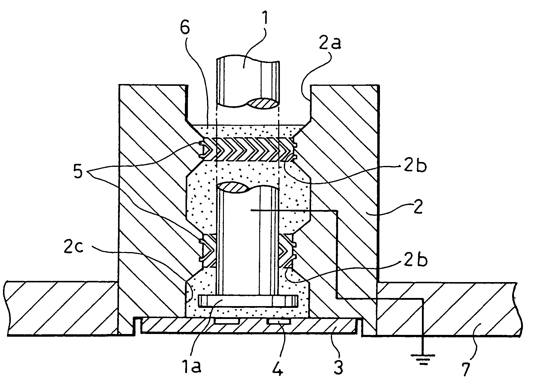
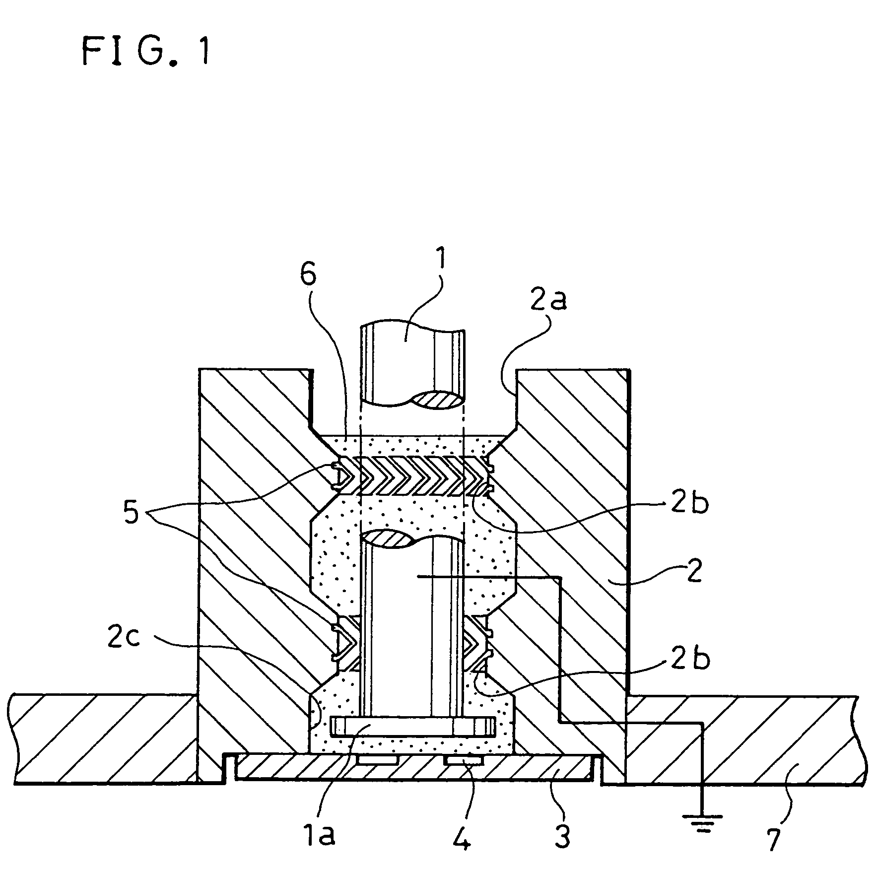
[0038]FIG. 1 is a cross-sectional view showing a fluid dynamic bearing in accordance with Embodiment 1 wherein a fluid dynamic bearing in accordance with the present invention is used for a hard disk drive (HDD) serving as one kind of a magnetic disk apparatus.

[0039]As shown in FIG. 1, the fluid dynamic bearing in accordance with Embodiment 1 comprises a shaft 1 configured so as to be rotatable, a sleeve 2, having a through hole 2a, for supporting this shaft 1 in the radial direction, a thrust plate 3 disposed so as to be opposed to the end face (the lower face in FIG. 1) of a flange portion 1a formed on one end of the shaft 1, and a lubricant 6. The lubricant 6 is filled in the clearance between the outer circumferential face of the shaft 1 and the inner face of the through hole 2a of the sleeve 2 and in the clearance between the flange portion 1a and the thrust plate 3. The sleeve 2 is formed so as to be integrated with a base 7 substantially secured to the housing of the hard dis...

embodiment 2

[0055]A case wherein a fluid dynamic bearing in accordance with Embodiment 2 of the present invention is used for a hard disk drive (HDD) serving as another magnetic disk apparatus will be described below referring to the accompanying FIG. 2.

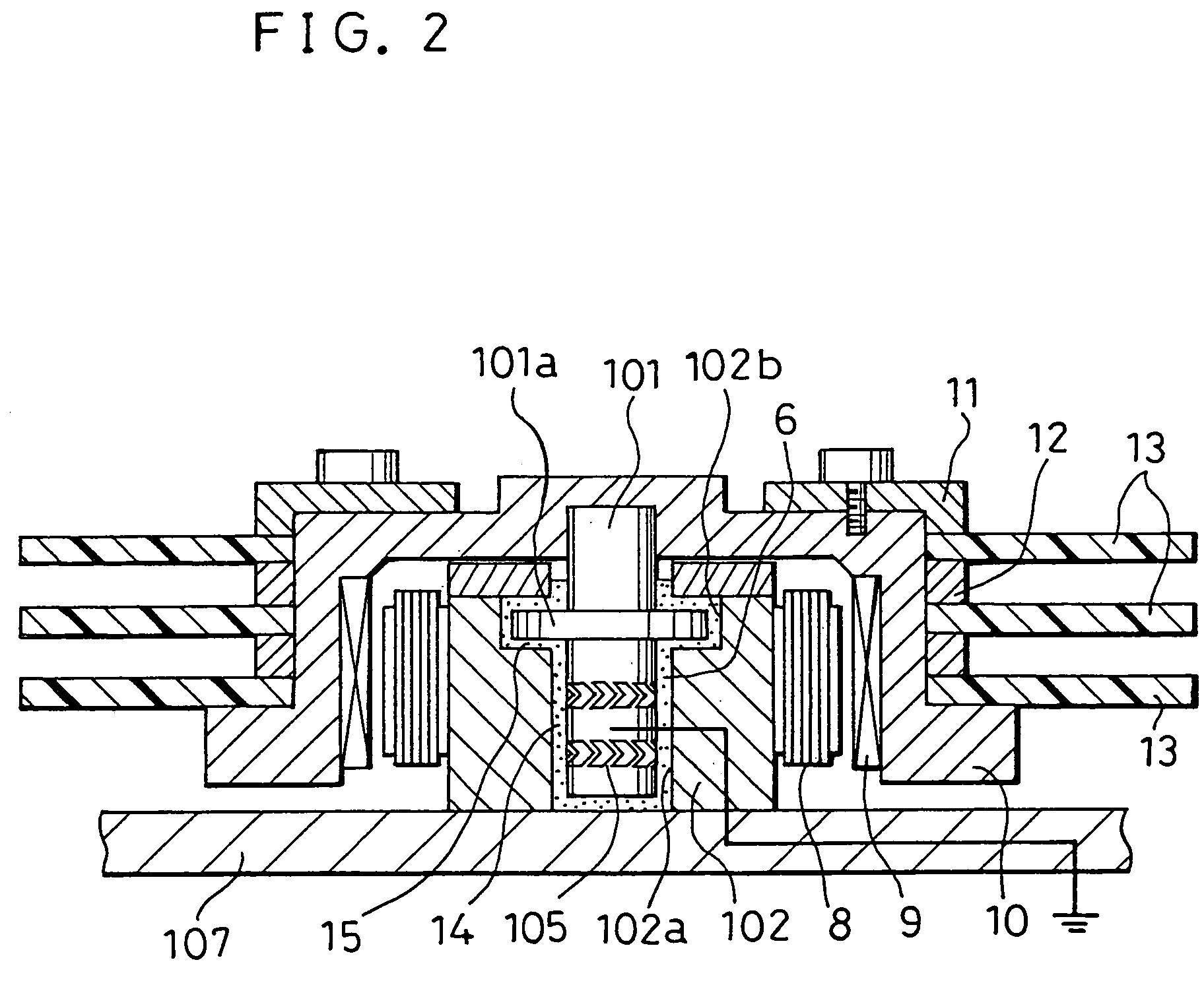
[0056]FIG. 2 is a cross-sectional view showing a case wherein the fluid dynamic bearing in accordance with Embodiment 2 of the present invention is used for a hard disk drive (HDD) serving as one of magnetic disk apparatuses.

[0057]As shown in FIG. 2, in the fluid dynamic bearing in accordance with Embodiment 2, three magnetic disks 13, 13 and 13 are stacked on a hub 10 and secured with a clamp 11. Spacers 12 are provided between the magnetic disks 13 so that the magnetic disks 13 are disposed at desired intervals. A rotor magnet 9 is provided on the inner circumferential face of the hub 10 having an inverted U-shaped cross-section. This rotor magnet 9 and a stator coil 8 provided on the outer circumferential face of a sleeve 102 serving as a sta...

embodiment 3

[0066]A case wherein a fluid dynamic bearing in accordance with Embodiment 3 of the present invention is used for the hard disk drive (HDD) shown in FIG. 1 will be described below. The fluid dynamic bearing in accordance with Embodiment 3 has the substantially same configuration as that of the fluid dynamic bearing in accordance with the above-mentioned Embodiment 1, except the configuration of the lubricant.

[0067]The base oil of the lubricant in accordance with Embodiment 3 is not limited in particular, provided that it has the viscosity required for the generation of dynamic pressure in the bearing; it is a mineral oil or a synthetic oil; a lubricant, such as α-olefin, ester oil, silicone oil or fluorine-based oil, is used as a synthetic oil. The same base oil as the base oil of the lubricant in accordance with Embodiment 1 was used as the base oil of the lubricant in accordance with Embodiment 3. In the Embodiment 3, linear alkyl sulfonate is added to this base oil. The lubricant...


PUM

PropertyMeasurementUnit
electrical resistivityaaaaaaaaaa

Abstract

In the present invention, in order to provide a fluid dynamic bearing, having heat resistance, wherein the electrical charging on a rotation portion is prevented and the torque loss caused by a lubricant is made lower, an ionic liquid or the like is added to the lubricant filled in the clearance between the opposed faces of a shaft and a sleeve unit as an electrical conductivity imparting agent.

Description

BACKGROUND OF THE INVENTION[0001]The present invention relates to a fluid dynamic bearing wherein a lubricant filled in the clearance between a shaft and a sleeve for rotatably supporting the shaft is used as a pressure generation liquid. The fluid dynamic bearing in accordance with the present invention is used, for example, for magnetic disk drive spindle motors in magnetic disk apparatuses, polygon-mirror rotation drive apparatuses in high-speed digital copiers, laser printers, and rotary magnetic head apparatuses in video tape recorders, etc. More particularly, the present invention relates to a fluid dynamic bearing having means for preventing the charging of static electricity in the rotation portion thereof during high-speed rotation, and a magnetic disk apparatus.[0002]The fluid dynamic bearing comprises at least a shaft, a sleeve for rotatably supporting this shaft and a lubricant serving as a lubrication fluid filled in the clearance between the shaft and the sleeve. In th...

Claims


Application Information

Patent Timeline
Patent Type & Authority Patents(United States)
IPC IPC(8): F16C17/02F16C17/10F16C33/10F16C41/00G11B19/20H02K5/167H02K7/08
CPCF16C17/026F16C33/107G11B19/2018F16C17/107C10N2220/04F16C2370/12C10N2020/077
Inventor OHNO, HIDEAKI
Owner PANASONIC CORP
Why Eureka
Try Eureka