Magnetic resonance imaging apparatus and magnetic resonance imaging method

a magnetic resonance imaging and magnetic resonance imaging technology, applied in the field of magnetic resonance imaging apparatus and magnetic resonance imaging method, can solve the problems of non-uniform tomographic image produced based on magnetic resonance signals received by surface coils, the sensitivity distribution of receive coils is not uniform over the whole imaged region, and the reception sensitivity decreases. achieves the effect of facilitating accurate tomographic imaging and accurate calculation of the sensitivity distribution of receive coils

Inactive Publication Date: 2006-03-21
GE MEDICAL SYST GLOBAL TECH CO LLC
View PDF14 Cites 19 Cited by
  • Summary
  • Abstract
  • Description
  • Claims
  • Application Information

AI Technical Summary

Benefits of technology

[0017]It is therefore an object of the present invention to provide a magnetic resonance imaging apparatus and magnetic resonance imaging method that facilitates accurate calculation of the sensitivity distribution of a receive coil, and facilitates accurate tomographic imaging on a subject.
[0022]According to the present invention, there are provided a magnetic resonance imaging apparatus and magnetic resonance imaging method that facilitate accurate calculation of the sensitivity distribution of a receive coil, and facilitate accurate tomographic imaging on a subject.

Problems solved by technology

The surface coil has, however, a property of decreasing reception sensitivity with increasing distance from the magnetic resonance signal source in the subject, and its sensitivity distribution is not uniform over the whole imaged region.
Thus, there is a problem of a tomographic image produced based on magnetic resonance signals received by the surface coil becoming non-uniform.
The volume coil, however, sometimes has a markedly non-uniform sensitivity distribution due to the permittivity effect especially when used in an ultra-high magnetic field of 3 Teslas or more, and at that time it cannot produce an adequately uniform image.
In such a case, the sensitivity distribution of a surface coil over the whole imaged region as described above cannot be calculated beforehand, because there is no receive coil having a uniform sensitivity.
In the conventional techniques, as described above, the sensitivity distribution of the receive coil is sometimes inaccurately calculated, and it is sometimes difficult to capture an accurate tomographic image of a subject.

Method used


Image

  • Magnetic resonance imaging apparatus and magnetic resonance imaging method
  • Magnetic resonance imaging apparatus and magnetic resonance imaging method
  • Magnetic resonance imaging apparatus and magnetic resonance imaging method

Examples


embodiment 1

[0035]The configuration of a magnetic resonance imaging apparatus of Embodiment 1 in accordance with the present invention will be described hereinbelow.

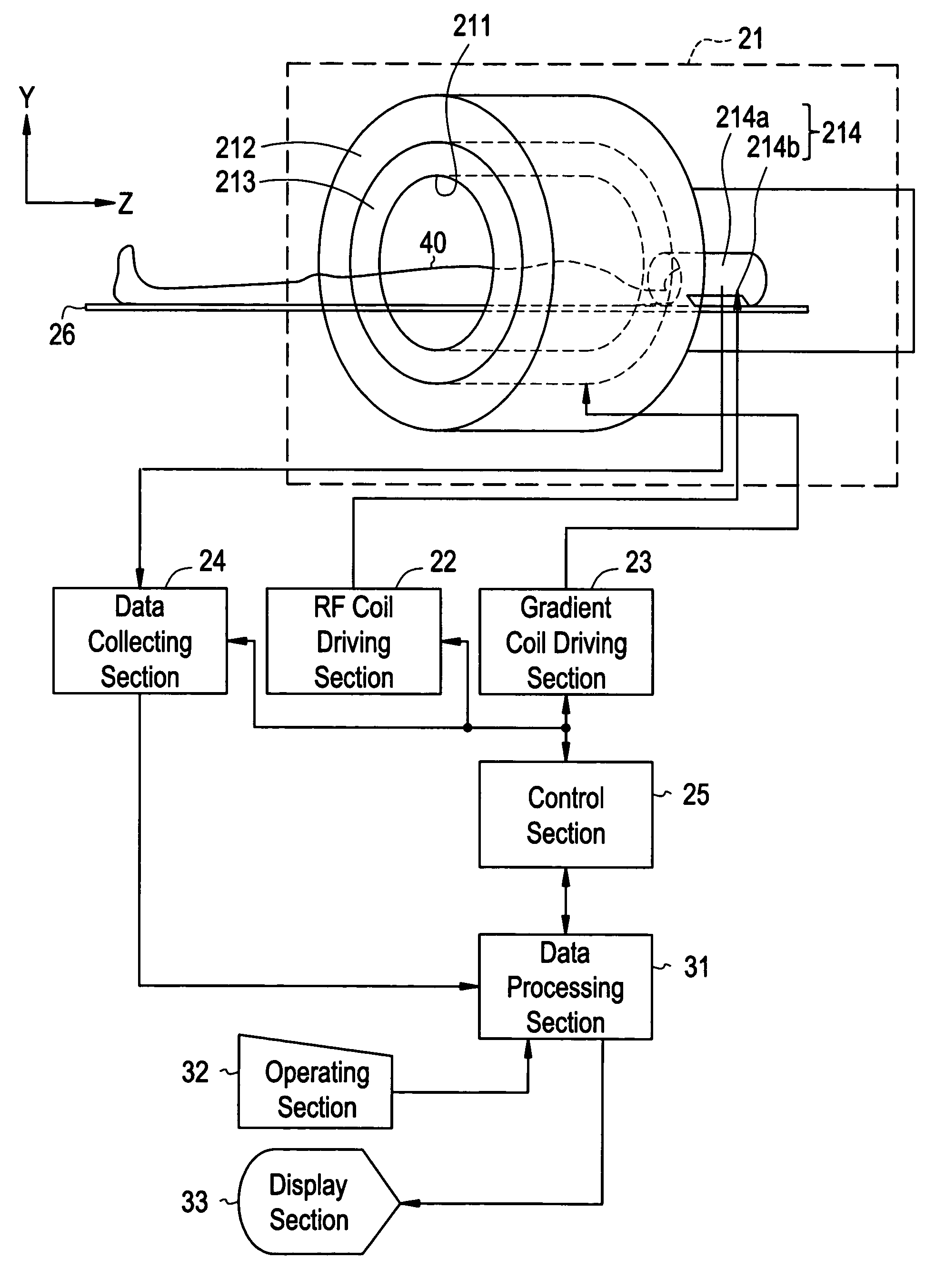
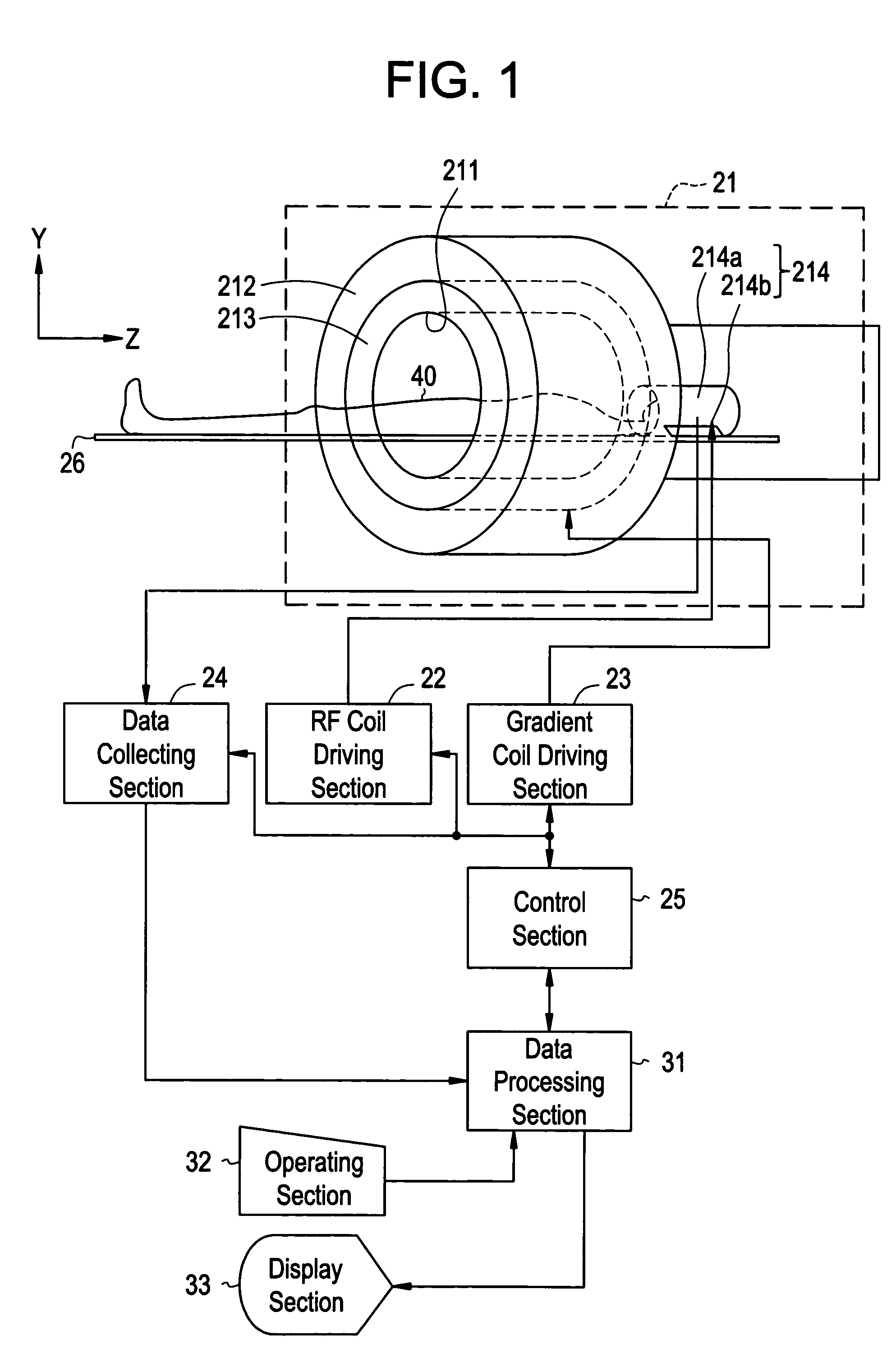
[0036]FIG. 1 is a block diagram showing the configuration of a magnetic resonance imaging apparatus 1 of Embodiment 1 in accordance with the present invention.

[0037]As shown in FIG. 1, the magnetic resonance imaging apparatus 1 comprises a magnet system 21, an RF (radio frequency) driving section 22, a gradient driving section 23, a data collecting section 24, a control section 25, a cradle 26, a data processing section 31, an operating section 32, and a display section 33.

[0038]These components will be described one by one hereinbelow.

[0039]The magnet system 21 comprises a static magnetic field magnet section 212, a gradient coil section 213, and an RF coil section 214. The static magnetic field magnet section 212 and gradient coil section 213 are disposed around a cylindrical bore 211, which is an imaging space. The RF coil sectio...

embodiment 2

[0092]The configuration of a magnetic resonance imaging apparatus of Embodiment 2 in accordance with the present invention will be described hereinbelow.

[0093]FIG. 5 is a block diagram showing components executing image processing in the data processing section 31 in Embodiment 2.

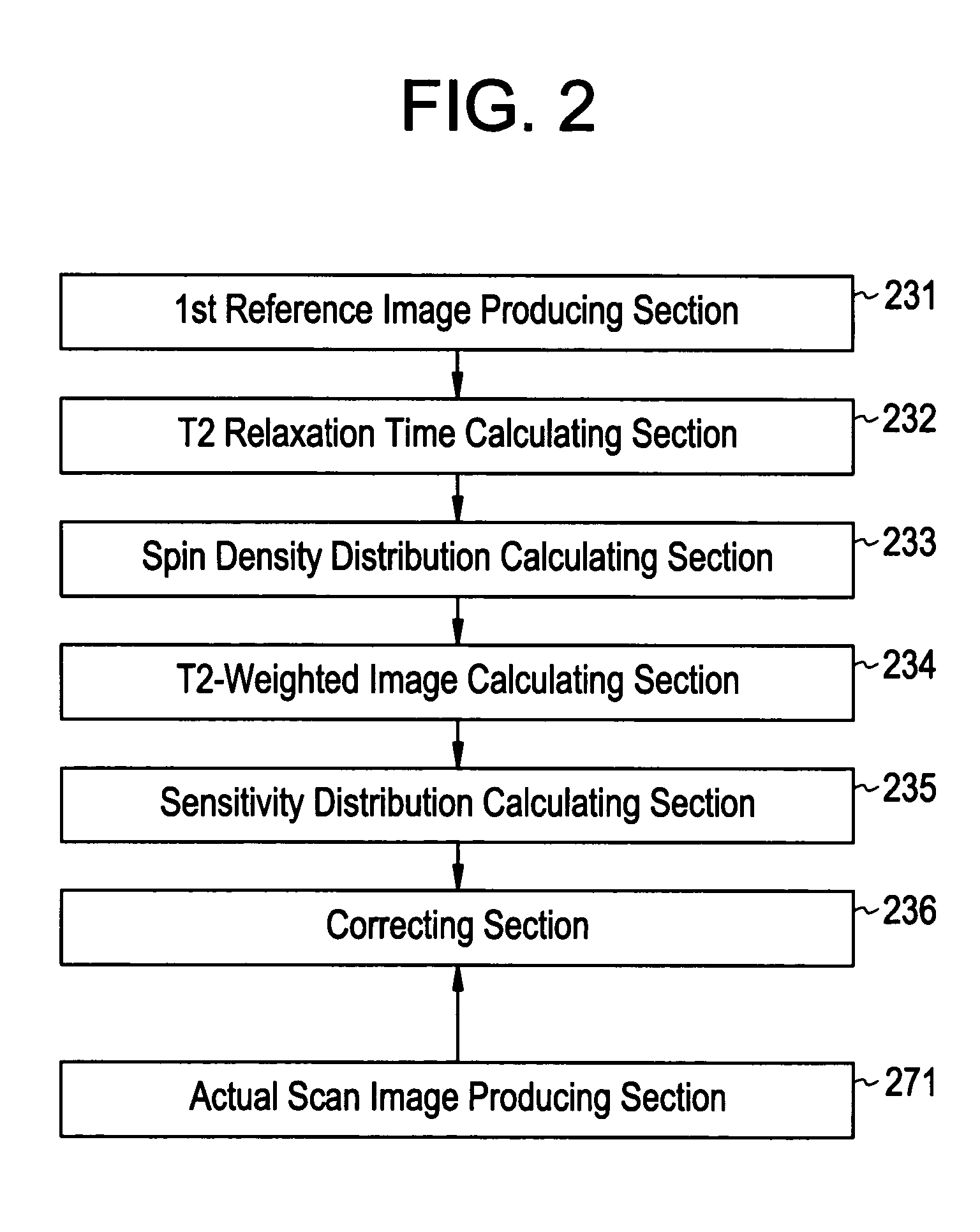
[0094]As shown in FIG. 5, the data processing section 31 of Embodiment 2 comprises the first reference image producing section 231, T2 relaxation time calculating section 232, spin density distribution calculating section 233, T2-weighted image calculating section 234, sensitivity distribution calculating section 235, correcting section 236, a second reference image producing section 241a, a third reference image producing section 241b, a T1 relaxation time calculating section 242, and the actual scan image producing section 271.

[0095]The magnetic resonance imaging apparatus of Embodiment 2 is similar to that of Embodiment 1 except that it has the second reference image producing section 241a, third referen...

embodiment 3

[0123]The configuration of a magnetic resonance imaging apparatus of Embodiment 3 in accordance with the present invention will be described hereinbelow.

[0124]FIG. 7 is a block diagram showing components executing image processing in the data processing section 31 in Embodiment 3.

[0125]As shown in FIG. 7, the data processing section 31 comprises the first reference image producing section 231, T2 relaxation time calculating section 232, spin density distribution calculating section 233, T2-weighted image calculating section 234, sensitivity distribution calculating section 235, correcting section 236, second reference image producing section 241a, third reference image producing section 241b, T1 relaxation time calculating section 242, a fourth reference image producing section 251, an apparent diffusion coefficient (ADC) calculating section 252, and the actual scan image producing section 271.

[0126]The magnetic resonance imaging apparatus of Embodiment 3 is similar to that of Embod...


PUM


Abstract

A method for calculating a sensitivity distribution of a receive coil and taking a tomographic image of a subject, based on magnetic resonance signals received by a surface coil in an imaging sequence with a plurality of different echo times TE1 and TE2 in a reference scan, a plurality of reference images are produced by a first reference image producing section; and based on the plurality of reference images, a T2 relaxation time is calculated by a T2 relaxation time calculating section. Then, based on the calculated T2 relaxation time, a T2-weighted image at the echo time TE2 is calculated by a T2-weighted image calculating section, and thereafter, based on the reference image and T2-weighted image at the echo time TE2, a sensitivity distribution is calculated by a sensitivity distribution calculating section. Based on the sensitivity distribution, a tomographic image by an actual scan is corrected by a correcting section.

Description

CROSS REFERENCE TO RELATED APPLICATIONS[0001]This application claims the benefit of Japanese Application No. 2003-424441 filed Dec. 22, 2003.BACKGROUND OF THE INVENTION[0002]The present invention relates to a magnetic resonance imaging apparatus and magnetic resonance imaging method, and more particularly to a magnetic resonance imaging apparatus and magnetic resonance imaging method for correcting a tomographic image of an imaged region in a subject produced based on magnetic resonance signals emitted from the imaged region and received by a receive coil in an actual scan, with reference to a sensitivity distribution of the receive coil in the imaged region created in a reference scan.[0003]Magnetic resonance imaging (MRI) apparatuses are widely used especially in medical applications because of their capability of capturing a tomographic image of a subject using the nuclear magnetic resonance (NMR) phenomenon.[0004]In a magnetic resonance imaging apparatus, the subject is placed w...

Claims


Application Information

Patent Timeline
Patent Type & Authority Patents(United States)
IPC IPC(8): G01V3/00G01R33/54A61B5/055G01R33/32G01R33/341G01R33/50
CPCG01R33/50G01R33/341G01R33/246A61B5/055
Inventor KABASAWA, HIROYUKI
Owner GE MEDICAL SYST GLOBAL TECH CO LLC
Why Eureka
Try Eureka