Signal transmission/reception system of orthogonal frequency division multiplexing

a signal transmission and reception system technology, applied in the field of signal transmission/reception system of orthogonal frequency division multiplexing, to achieve the effect of large distortion, less susceptible, and high error correction performan

Inactive Publication Date: 2006-03-21
KOKUSA ELECTRIC CO LTD +1
View PDF7 Cites 14 Cited by
  • Summary
  • Abstract
  • Description
  • Claims
  • Application Information

AI Technical Summary

Benefits of technology

[0045]A possible method of addressing this problem would involve estimating the phase and magnitude of a reference signal vector at a carrier position at which no SP carrier exists out of a band, from the phase and magnitude of a reference signal vector for an SP carrier near an end of the band, and extrapolating a reference signal vector at that carrier position to reduce a distortion in waveform possibly occurring in an LPF.
[0050]Advantageously, according to the present invention, it is possible to configure a satisfactory OFDM-based transmission apparatus, transmitting information codes using a plurality of carriers, which is immune to a change in environment of a transmission system.
[0052]Also, for demodulating carriers in both ends of the band of the signal transmission, the transmission apparatus of the present invention requires a demodulator circuit adapted to a modulation scheme different from a demodulator circuit adapted to a modulation scheme for carriers in a central region of the band. However, by modulating the both ends at the band in accordance with the same synchronous modulation scheme as same as the carriers intermediate of the transmission band, a common circuit can be shared only by changing signal point positioning for the demodulator circuit, so that an increase in circuit scale can be substantially ignored.
[0054]However, in one embodiment of the present invention, carriers existing in this region, which have particularly larger distortions, are modulated in accordance with the differential modulation scheme that is free from the influence of distortions in reference signal vectors, or in accordance with a synchronous modulation scheme having a low number of multilevel, which is less susceptible to the distortions, and further corrected using an error correction code having high error correction performance, thereby making it possible to configure an OFDM-based modulation apparatus which employs the modulation scheme that features a low code error rate.

Problems solved by technology

However, the aforementioned problem arises since a required number of carriers are not always available.

Method used


Image

  • Signal transmission/reception system of orthogonal frequency division multiplexing
  • Signal transmission/reception system of orthogonal frequency division multiplexing
  • Signal transmission/reception system of orthogonal frequency division multiplexing

Examples


first embodiment

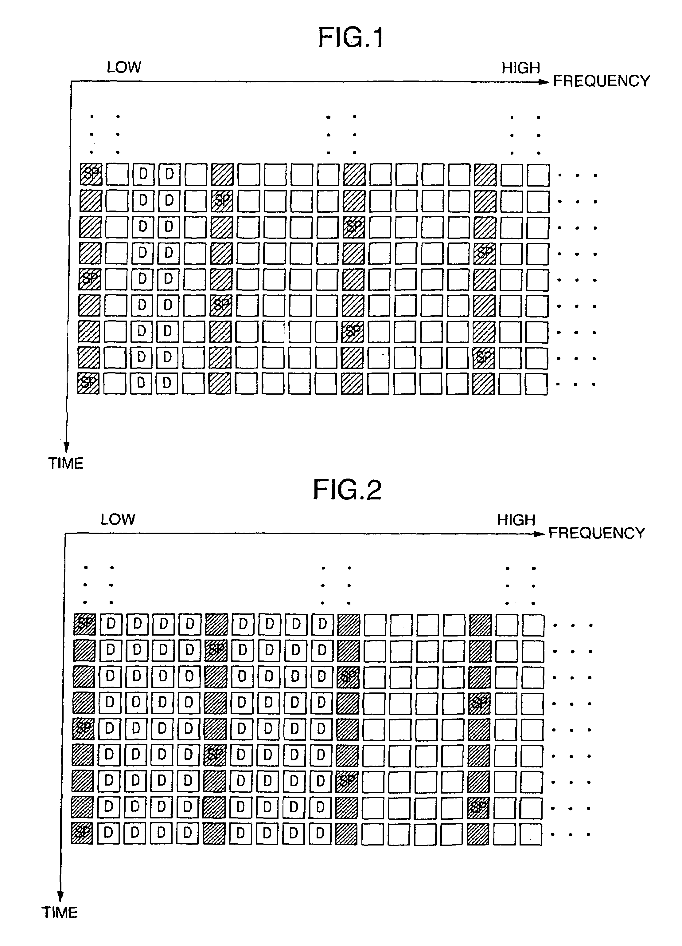
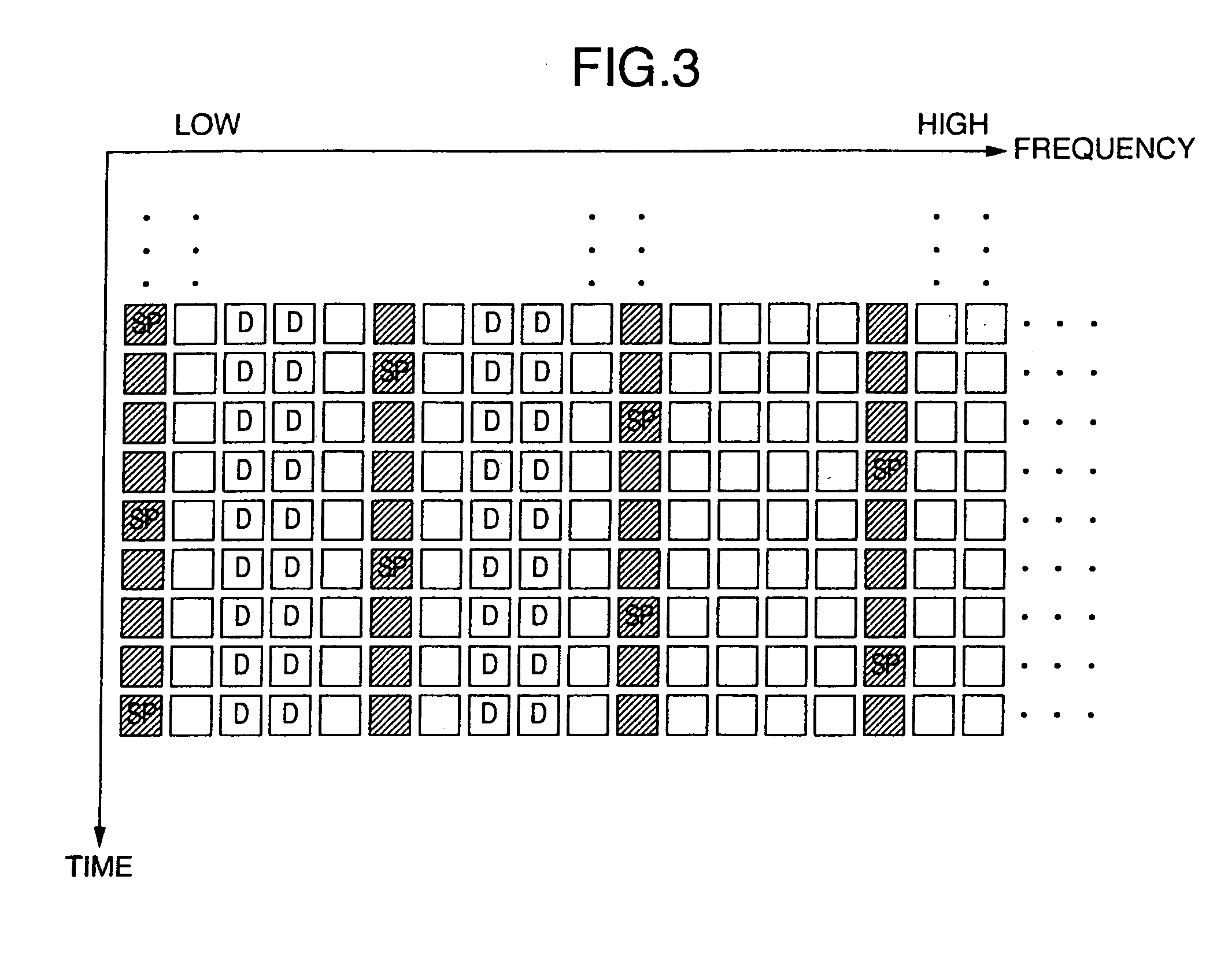
[0072]FIG. 1 shows an exemplary structure of carriers in the present invention, wherein the horizontal direction represents the frequency, and the vertical direction represents the lapse of time, as is the case with FIG. 7. Squares “□” arrayed in the horizontal and vertical directions each represent one carrier. Thus, one row of carriers “□” arranged in the laterial direction represents one symbol which forms part of an OFDM signal.

[0073]Further, a carrier “□” with “SP” denoted within the square represents the position of a carrier for a pilot signal which is used for reproducing a reference signal during demodulation, while a carrier without any notation within the square represents the position of a carrier for a signal modulated in accordance with the 64 QAM scheme, also as is the case with FIG. 7.

[0074]The interval between SP carriers in the first embodiment of FIG. 1 may be any arbitrary number of columns of carriers, including three, as in the terrestrial digital broadcasting ...

second embodiment

[0089]From the foregoing, particularly largely distorted carriers are removed from C-carriers modulated in accordance with a synchronous modulation scheme with a higher number of multilevel, susceptible to noise and distortions in reference signal vectors, and mapped to D-carriers, likewise in the Consequently, as compared with the prior art which includes information codes decoded from carriers using largely distorted reference signal vectors, this embodiment can reduce a code error rate of information codes decoded from C-carriers modulated in accordance with the synchronous modulation scheme.

[0090]Also, in the second embodiment, the D-carriers are modulated in accordance with a synchronous modulation scheme with a lower number of multilevel, relatively immune to noise and distortions in reference signal vectors, even if this is the same synchronous modulation scheme as that used for modulating C-carriers. Therefore, a large distortion in a reference signal vector for this carrie...

third embodiment

[0106]In a specific implementation of the third embodiment, for example, as illustrated in FIG. 5, the error correction coding circuit 50 associated with information codes transmitted by C-carriers uses a ¾ convolutional code for the error correction code, while the error correction coding circuit 52 associated with an AC code transmitted by a D-carrier uses a ½ convolutional code, which has higher error correcting performance than the ¾ convolutional code for use with the information codes transmitted by the C-carriers, for the error correction code.

[0107]Though not particularly noted in the foregoing description, the value of the predetermined number M for defining the width of a boundary region of ends of the signal transmission band may be determined from an S / N (Signal to Noise) ratio for a distortion of the interpolation filter, and a C / N (Carrier to Noise) ratio which should be required in 64 QAM, assuming, for example, the modulation in accordance with 64 QAM, in which case ...


PUM


Abstract

A transmission apparatus of orthogonal frequency division multiplexing for multiplexing a plurality of carriers orthogonal to one another to transmit a modulated signal. The transmission apparatus includes a first modulator for outputting a code modulated in accordance a modulation scheme which can be applied with a synchronous detection for demodulation, a second modulator for outputting a code modulated in accordance with a modulation scheme different from the modulation scheme associated with the first modulator, and a distributing circuit for distributing the codes modulated by the first and second modulators to a plurality of carriers. The distributing circuit distributes the code modulated by the second modulator to all or some of carriers existing within a predetermined number of columns from at least one of both end regions of a signal transmission frequency band, and the code modulated by the first modulator to the remaining carriers.

Description

BACKGROUND OF THE INVENTION[0001]The present invention relates to a signal transmission / reception system of orthogonal frequency division multiplexing, and more particularly, to a signal transmission / reception system of orthogonal frequency division multiplexing based on synchronous modulation such as a 64 QAM (Quadrature Amplitude Modulation) scheme.[0002]In recent years, in the field of radio devices, the OFDM scheme has been in the limelight as a modulation scheme immune to multipath fading. A large number of applied studies on the OFDM are now under progress in the fields of next-generation television broadcasting, FPU (Field Pickup Unit), radio LAN and so on in many countries including European countries and Japan.[0003]Here, the OFDM (Orthogonal Frequency Division Multiplexing) scheme is an acronym for an orthogonal frequency division multiplexing modulation in which information codes are transmitted by using a plurality of carriers orthogonal to one another. The trends of dev...

Claims


Application Information

Patent Timeline
IPC IPC(8): H04J11/00H04L1/00H04L25/02H04L27/26
CPCH04L5/0048H04L25/0226H04L25/0232H04L27/2071H04L27/3455H04L27/2602H04L27/0008H04L27/2627
Inventor AKIYAMA, TOSHIYUKITSUKAMOTO, NOBUOIKEDA, TETSUOMIOKABE, SATOSHI
Owner KOKUSA ELECTRIC CO LTD
Why Eureka
Try Eureka